Arduino Radio Board
Kit List
| List | Quantity |
|---|---|
| PCB Board | 1 |
| 2x4 pin header female | 1 |
| 2x3 pin header male | 1 |
| 1x6 pin header female | 2 |
| 1x8 pin header female | 2 |
| 433mhz coil antenna | 1 |
| 28P IC socket | 1 |
| 7805 regulator | 1 |
| 1x8 2.00mm pitch pin header male | 2 |
| 1x8 2.00mm pitch pin header female | 2 |
| green and red leds | 2 |
| push button | 1 |
| 7333 3.3V regulator | 1 |
| 1N5819 diode | 1 |
| 10K resistor | 1 |
| 330R resistor | 1 |
| 104 0.1UF capacitor | 4 |
| 22 22pF capacitor | 4 |
| ceramic fuse | 1 |
| 16Mhz crystal | 1 |
| 100uf capacitor | 3 |
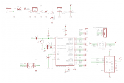
Schematic
Pin Definitions
| Pins | Description |
|---|---|
| D2 | to DIO0 pin of RFM69 |
| D3 | to IRQ pin of Nrf24l01 |
| D8 | to CE pin of Nrf24l01 |
| D9 | to CS pin of Nrf24l01 |
| D10 | to SEL pin of RFM69 |
