Category:AVR SDK
ToolChain
- AVR Programmer
- Arduino Dev Board
- AVR Dev Board
Flash Tool
Complier
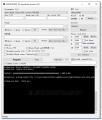
- Winavr WinAVR: Install the programmed, and test the AVRDUDE like below, run the cmd.exe in start menu.
Programmer
- ProgISP Very Powerful and useful burning tool, same as AVR fight, eXtreme Burner, etc, these tools are also a kind of Avrdude GUI tools, provide a windows interface instead of avrdude command line.Click the RD to read the chip, you can check the wiring by doing so.
- AVR_fighter
Fuse Set
You know about flash, eeprom and RAM as parts of the chip. What I did not mention is that there are also 3 bytes of permanent (by permanent I mean that they stick around after power goes out, but that you can change them as many times as you'd like) storage called the fuses. The fuses determine how the chip will act, whether it has a bootloader, what speed and voltage it likes to run at, etc. Note that despite being called 'fuses' they are re-settable and dont have anything to do with protection from overpowering (like the fuses in a home).
Programing
You could grab the demo code from File:Had AVRtut 2-master.zip, and programming the hex file into your chip. This code is for atmega 168, you should have the postive pin of led to the pin 2 of atmega 168 and negative to a resistor (180 or 330 Ohm), and then go to GND.
You should see the LED blinking once the hex programmed.
Memory Map
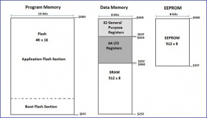
The memory map of a microcontroller is a diagram which gives the size, type and layout of the memories that are available in the microcontroller. The information use to construct the memory map is extracted from the datasheet of the microcontroller.
The diagram below gives the memory map for the ATMega8515 AVR 8-bit Microcontroller from Atmel. The ATMega8515 microcontroller contains three(3) blocks of memory: Program Memory, EEPROM Memory and Data Memory.
Data Memory Contains:
- 32 8-bits General Purpose
- 64 8-bits Input/Output Registers
- 512 8-bits SRAM space
Program Memory Contains:
- 8K byte Flash Memory
- Organized as 4K-16bits space
EEPROM Memory Contains:
- 512 8-bits EEPROM space
Demo Starting Code
snippet 1
#ifndef F_CPU
#define F_CPU 16000000UL // 16 MHz clock speed
#endif

#include <avr/io.h>
#include <util/delay.h>

int main(void)
{
  DDRC = 0xFF; //Nakes PORTC as Output
  while(1) //infinite loop
  {
    PORTC = 0xFF; //Turns ON All LEDs
    _delay_ms(1000); //1 second delay
    PORTC= 0x00; //Turns OFF All LEDs
    _delay_ms(1000); //1 second delay
  }
}
snippet 2
#include <avr/io.h>
#include <avr/interrupt.h>

int main(void)
{

  //Setup the clock
  cli();            //Disable global interrupts
  TCCR1B |= 1<<CS11 | 1<<CS10;  //Divide by 64
  OCR1A = 15624;        //Count 15624 cycles for 1 second interrupt
  TCCR1B |= 1<<WGM12;     //Put Timer/Counter1 in CTC mode
  TIMSK1 |= 1<<OCIE1A;        //enable timer compare interrupt
  sei();            //Enable global interrupts

  //Setup the I/O for the LED

  DDRD |= (1<<0);     //Set PortD Pin0 as an output
  PORTD |= (1<<0);        //Set PortD Pin0 high to turn on LED

  while(1) { }          //Loop forever, interrupts do the rest
}

ISR(TIMER1_COMPA_vect)      //Interrupt Service Routine
{
  PORTD ^= (1<<0);        //Use xor to toggle the LED
}

