Category:DHT22
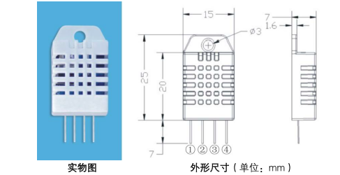
Dimension
Wiring
- VDD = Power Supply
- Uart data, double way
- NC
- GND

The AM2302 supply voltage range of 3.5V - 5.5V, and recommended supply voltage is 5V.
Data line SDA pin is tri-state sensor for reading and writing data. See detailed single-bus communication protocol description.
IIC communication
Single-bus communication (ONE-WIRE)
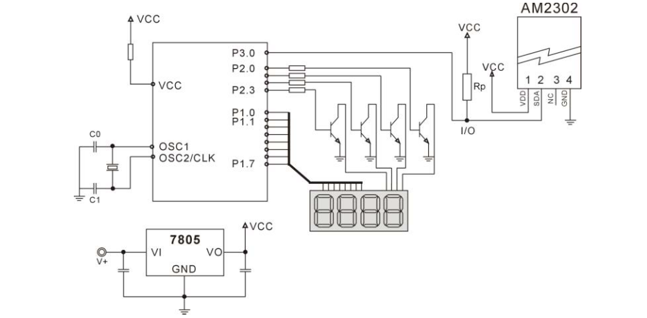
7.1 single bus typical circuit
Microprocessor AM2302 connection typical application circuit is shown in Figure 4. Single-bus communication mode, SDA pull-and micro-processing
The I / O port.
Single-bus communication Special Instructions:
1. Typical application circuit recommended cable length short 30 meters 5.1K pull-up resistor is greater than 30 meters, according to the actual situation
Condition to reduce the resistance of the pull-up resistor.
2. With 3.3V voltage supply cable length shall not be more than 30cm. Otherwise, the line voltage drop can cause the sensor supply,
Resulting in measurement bias.
3. The read sensor minimum interval 2S; reading interval less than 2s, may cause the temperature and humidity are not allowed or not a communication
Power and so on.
4. Each read out the temperature and humidity values are the result of the last measurement, For the real-time data, sequential read twice,
Recommended repeatedly reads the sensor and each read sensor interval is greater than 2 seconds to obtain accurate data.

7.2, single-bus communication protocol
◎ single bus Description
AM2302 device uses a simplified single bus communication. Single bus that only a single line, the data exchange system, controlled by the data line is completed. Device (microprocessor) through a drain open or tri-state port connected to the data line to allow the device to send data to release the bus, and let other devices use the bus; single bus usually require an external 5.1kO pull-up resistor, so that when the bus is idle, the state is high. Because they are the master-slave structure, only the host Call sensor, the sensor will acknowledge the host access to the sensor must be strictly followed the sequence of a single bus, if the chaotic sequence, the sensor will not respond to the host.
◎ send a single bus data definition
SDA is used for the communication between the microprocessor and the AM2302 and synchronization, single-bus data format that sending 40-bit data, MSB-first. Specific communication sequence shown in Figure 5, the communication format depicted in Table 5.
- Starting signal
- Responding signal
- humidity high bits
- humidity low bits
- temperature high bits
- temperature low bits
- CRC
IIC example
Example 1: 40-bit data received:
  0000 0010        1001 0010        0000 0001            0000 1101     1010 0010

Humidity 8-high humidity 8-low temperature 8-high temperature 8-low     CRC
Calculated as follows:
0000 0010 +1001 0010 +0000 0001 +0000 1101 = 1010 0010 (CRC)
The received data is correct:
Humidity: 0000 0010 1001 0010 = 0292H (hexadecimal) = 2 × 256 + 9 × 16 + 2 = 658
=> Humidity = 65.8% RH
Temperature: 0000 0001 0000 1101 = 10DH (hexadecimal) = 1 x 256 + 0 x 16 + 13 = 269
=> Temperature = 26.9 ° C
◎ Special Instructions:
When the temperature is below 0 ° C the highest position of the temperature data.
Example: -10.1 ° C expressed as 1,000,000,001,100,101
Temperature: 0000 0000 0110 0101 = 0065H (hexadecimal) = 6 × 16 +5 = 101
=> Temperature = -10.1 ° C
Example 2: 40-bit data received:
   0000 0010        1001 0010            0000 0001            0000 1101          1011 0010

Humidity 8-high    humidity 8-high     temperature 8-high    temperature 8-low        CRC
Calculated as follows:
0000 0010 +1001 0010 +0000 0001 +0000 1101 = 1010 0010 ≠ 1011 0010 (parity error)
The received data is not correct, give up, receive data again.
7.3 single-bus communication timing
User host (MCU) send a start signal (data bus SDA low for at least 800μs), AM2302 converted to high-speed mode from Sleep mode. After the end of the start signal to be host, AM2302 transmits a response signal sent 40bit data from the data bus SDA serial, first send byte high; the data sent followed humidity high, low humidity, the temperature is high, the temperature is low, the parity bit the end of the send data to trigger an information collection, the end of the acquisition sensor automatically goes to sleep mode, until the advent of the next communication.
The detailed timing signal characteristics are shown in Table 6, the single-bus communication timing diagram shown in Figure 6.
 Note: the temperature and humidity data read by the host from AM2302 always the last measurement value, such as the interval of the two measurements is very long, continuous read twice the value obtained to the second temperature and humidity values in real time, while two Rtake the minimum interval for 2s.
Signal Feature
| Symbol | Parameter | min | typ | max | unit |
|---|---|---|---|---|---|
| T be | host initiate signal pull-low time | 0.8 | 1 | 20 | ms |
| T go | host release main bus time | 20 | 30 | 200 | µS |
| T rel | responding low TTL time | 75 | 80 | 85 | µS |
| T reh | respoding high TTL time | 75 | 80 | 85 | µS |
| T LOW | signal 0, 1 low ttl time | 48 | 50 | 55 | µS |
| T H0 | signal 0 high ttl time | 22 | 26 | 30 | µS |
| T H1 | signal 1 high ttl time | 68 | 70 | 75 | µS |
| T en | sensor release main bus time | 45 | 50 | 55 | µS |
7.4 peripherals reading step example
The communication between the host and the sensor can be done through the following three steps to read data.
Step one
AM2302 (AM2302 after power after power to wait 2S over the unstable state, the reading device can not send any commands during this period), the test environment temperature and humidity data, and record the data, since the sensor automatically goes to sleep. The AM2302 SDA data line is pulled high by a pull-up resistor has maintained a high level, the AM2302 SDA pin is in the input state, the time to detect the external signal.
Step Two:
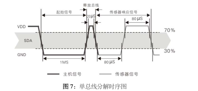
Microprocessor I / O settings for the output, while the output low and low hold time can not be less than 800us, the typical value is pulled low 1ms, then the microprocessor I / O set to input mode, release the bus. pull-up resistor, the microprocessor I / O AM2302 SDA data line also will be high, such as the bus master has released the AM2302 send a response signal, the output low for 80 microseconds, as a response signal, followed by the high level of the output 80 microseconds to inform the peripheral is ready to receive data, the signal transmitter is shown in Figure 7:

Step three:
AM2302 finished sending the response, followed by a continuous serial data bus SDA output 40-bit data, 40-bit data received by the microprocessor according to the change of the I / O level.
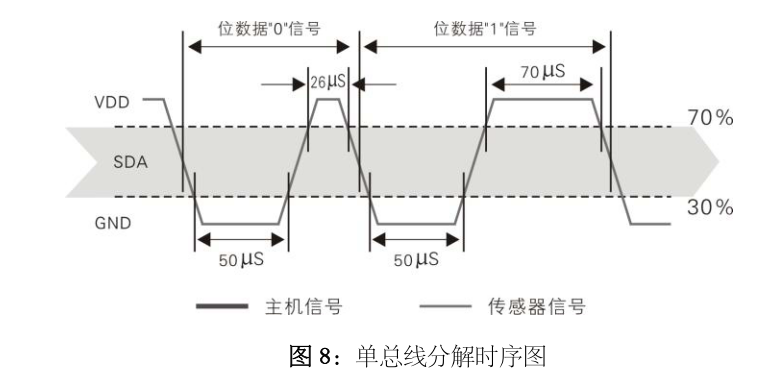
Bit data "0" of the format is: HIGH LOW plus 26-28 microseconds 50 microseconds;
Bit data "1" format: 50 ms in low 70 microseconds high;
Bit data "0", the bit data "1" format signal shown in Figure 8:

AM2302 data bus SDA output 40-bit data, continues to output low for 50 microseconds and changed to the input state goes in high pull-up resistor.AM2302 internal the retest environmental temperature and humidity data, and record data, test end-of-record, single-chip automatically enters sleep mode.MCU only after receipt of the initial letter of the host, only to re-awaken the sensor into the working state.

