AR9331
ED9331
- 16MB Flash, 64MB DDR2 RAM
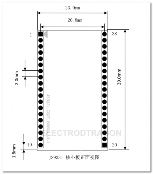
Pin Definition
Pin No. Name Description
- 1 VDD33 main power supply DC 3.3V input
- 2 VDD33 main power supply DC 3.3V input
- 3 GND main power supply
- 4 GND main power supply
- 5 GPIO26 standard GPIO
- 6 GPIO12 standard GPIO
- 7 GPIO27 standard GPIO, default is SYSTEM LED function
- 8 GPIO11 internal 10K pull-down resistor to ground, default is WIRELESS LED function, active high
- 9 GPIO17 internal 10K pull-up resistor to 2.6V, default is WAN LED function, active low
- 10 GPIO16 internal 10K pull-down resistor to ground, GPIO function
- 11 GND Ground
- 12 GPIO15 internal 10K pull-down resistor to ground, default is RESET/FACTORY NEW KEY function, active high
- 13 GPIO14 internal 10K pull-down resistor to ground, GPIO function
- 14 GPIO13 is internally connected to a 10K pull-up resistor to 2.6V. The default is the LAN1 LED function, which is active high.
- 15 GPIO1 internal 10K pull-up resistor to 2.6V, GPIO function
- 16 GPIO0 internal 10K pull-down resistor to ground, GPIO function
- 17 GND Ground
- 18 UART_RX serial port RX (usual for debugging)
- 19 UART_TX serial port TX (usual for debugging)
- 20 GPIO20 standard GPIO or I2S SD pin function, defaults to GPIO
- 21 GPIO19 standard GPIO or I2S WS pin function, defaults to GPIO
- 22 GPIO18 standard GPIO or I2S CK pin function, defaults to GPIO
- 23 GPIO21 standard GPIO or I2S MCK pin function, defaults to GPIO
- 24 GPIO22 standard GPIO or I2S MICIN pin function, defaults to GPIO
- 25 GND Ground
- 26 RX4_P Ethernet port 4 Receive positive terminal
- 27 RX4_N Ethernet port 4 Receive negative terminal
- 28 TX4_P Ethernet port 4 Send positive terminal
- 29 TX4_N Ethernet port 4 Send negative terminal
- 30 VDD20 Power over Ethernet Output
- 31 RX0_P Ethernet port 0 Receive positive terminal
- 32 RX0_N Ethernet port 0 Receive negative terminal
- 33 TX0_P Ethernet port 0 Send positive terminal
- 34 TX0_N Ethernet port 0 Send negative terminal
- 35 GND ground
- 36 USB_N USB Negative
- 37 USB_P USB Positive
- 38 GND Ground
- Note: For Ethernet port 4, the system is configured as the WAN port by default. Ethernet port 0, the system is configured as the LAN port by default.
Quick Start Guide
- Please use DC Power supply 5V (USB Female better use only for USB Slave device)
- Alternatively can usb USB-UART 3V3 / GND power supply directly
- Connect USB-UART serial Debugger TXD / RXD
- Core Module Triangle |> should point to USB direction
- Default AP stations WIFI is ZhuoTK_XXX, no password, manage web GUI LUCI at http://192.168.1.251/cgi-bin/luci
Start to flash latest pre-compiled firmware
- Flash method see here Category:Openwrt#Flash
- Find pre-compiled firmware here: https://bitbucket.org/e_dragon/openwrt-app/src
More detailed configurations please see openwrt category: https://www.electrodragon.com/w/Category:Openwrt
Schematic
Relevant Devices
| Device | Flash | RAM | Core | Reference |
|---|---|---|---|---|
| tl-wr720n_v3 | 4MB | 32MB | AR9331 | https://openwrt.org/toh/hwdata/tp-link/tp-link_tl-wr720n_v3 |
| tl-wr710n_v2.1 | 8MB | 32MB | AR9331 | https://openwrt.org/toh/hwdata/tp-link/tp-link_tl-wr710n_v2.1 |
Software
SSH, WinSCP/SCP protocl,
- Default login 192.168.1.251, user password both root
- For more package installation guide please see OPKG
- For mounting USB device pelase see on this page Mount


