ESP Relay Board Hardware
List of the boards
- ESP Relay Board SPST - AC in, Single status relay
- ESP Relay Board SPDT - AC in, Dual status relay
- ESP Relay Board IL - AC in, Relay with extra protections
- ESP Relay Board VDC - DC in, VIN 5-28V
- ESP Light - 12/24V DC Vin, LED strips or WS2812 control
Consistent Functions
IIC: IO4 and IO5
- IO4 and IO5 hs pull up resistors for IIC bus to use
- Demo code for IIC OLED screen for LUA can be found at nodemcu github, /master/lua_examples/u8glib/ this folder, or click here to browse.
- To remove the pull-up resistor, find the 2x two-very-close-pin on the right side of break away header pin 4 and pin 5, use knife to cut them, then 4.7K resistor will be disconnected. Also can add solder to re-connect them later.
DHT Sensor
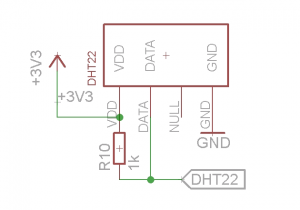
- Please connect the board to sensor by wires, because the PCB and relays will generate heats!!
- DHT22 support plug on to use, feel free to use wires or socket to settle the DHT sensor, pin definition is 3V3, data, NC and GND
- Default firmware has DHT module enable, upload example code will work directly. demo code here., or download lua sketch File:DHT22.zip, in esplorer run DHT22.lua direct to read temperature humidity
General Pin Definition
- Pin Definition for standard esp relay board, relay VDC board, relay SPDT board.
| ESP8266 Pins | Board Pins | Note | Function |
|---|---|---|---|
| IO12 | Relay 1 (or 2) | - | relay 10A load max. |
| IO13 | Relay 2 (or 1) | - | relay 10A load max. |
| IO16 | Status LED | - | - |
| IO14 | reserved DHT22 socket | pull-up 10K resistor | |
| IO4 (board silk print maybe wrong with IO5, please check) | DHT22 | pull-up 4.7K resistor, can be disconnected | |
| IO5 (board silk print maybe wrong with IO4, please check) | DHT22 | pull-up 4.7K resistor, can be disconnected | |
| IO0 | button BTN2 | pull-up 10K resistor | Hold down then power up to enter into flash mode |
| IO2 | button BTN1 | - | programmed for clear config from code version 1.2 |
| IO15 | - | - | - |
Documents
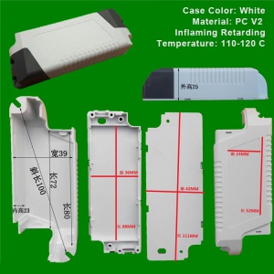
- Case size see on the image.
Projects (if you want list please let me know)
Further Read
- Relay circuit protection - Relay#Circuit_Protction

