ESP Relay Board SPST
Board Configuration
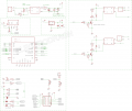
- General board configuration
Features
- Based on ESP-12F ESP8266 Wifi Board
- This relay board use one AC input, and supports two relay AC output
- Use mature AC-DC power module
- Plastic enclosure design support, package includes the plastic case
- Two Lead out buttons BTN1 and BTN2
- Two relay indication LEDs
- One status LED, indicating connecting status in demo code
- Resevered design for temperature sensor DHT22
- Screw terminal which are easy for wiring tput
Hardware Update Logs ==
Update Log for ESP Relay Board
Update R1.6
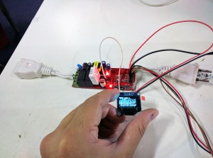
- Optmized lead out pins, IO4, IO5 used for IIC bus, see the demo image here.
Updated R1.5:
- Optimized board layout, replace a few higher quality parts
Updated version R1.1:
- Fix isolation and current drop issue on old version, which cause the ESP-wifi board may have a 5% chance to reset/restart when you switch relays On/Off very very frequently. R1.1 version is not absolutely can be eliminated this issue since the onboard AC-DC module has a limit, but the probability of this problem should be controlled to the least, low to one percent.
- Maximum trace design for current passing, 2MM trace width to let 2A current pass through roughly for two relays together, so either 2A for running one channel device or 1A for two device. also open trace without soldermask, you can add more solders to get even higher current passing.


