AVR Dev Board
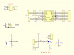
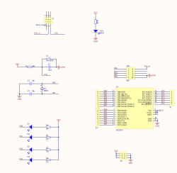
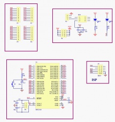
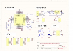
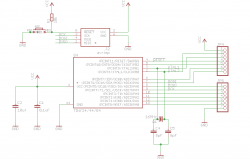
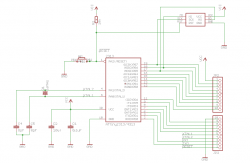
Schematic Collection
BOM list for Atmega 8 DIP Kit Board
| Part Type | Designator | Footprint | Description | Direction |
|---|---|---|---|---|
| 0.1uF | C9 | 104DIP | DIP 104 | No |
| 104 | C5, C4 | 104DIP | solder 104 Cap | No |
| 22P | C2, C1 | 30P-DIP | solder 22pf Cap | No |
| 1K | R2 | AXIAL0.4 | solder 1K Resistor | No |
| 10K | R1 | AXIAL0.4 | solder 10K Resistor | No |
| 7.2728M | X1 | SIP3 | Soldering three holes socket, and plug the crystal in | No |
| SW-PB | S1 | SW-PB6 | Soldering switch | No |
| 5HEADER | J9 | SIP5 | no soldering, save for further use | No |
| SIP6 | J3, J5 | SIP6 | no soldering, save for further use | No |
| SIP4 | J8 | SIP4 | no soldering, save for further use | No |
| 14-HEADER | J10 | SIP-14 | soldering 14P break-away header | No |
| SIP4 | J6 | SIP4 | soldering 4P break-away header | No |
| SIP6 | J2 | SIP6 | soldering 6P break-away header | No |
| ATMEGA8 | U1 | DDIP28 | Soldering IC socket, and plug the atmega8 IC into it | Yes |
| IDC10 | J1 | IDC10-1 | Soldering 10P Box header | Yes |
| LED | D2 | LED.3 | Soldering LED | Yes |
| POWER | J20 | DC3 | Soldering DC power supplier | No |
| 100uF/16V | C3 | 10uF-25V | Soldering 100UF cap | Yes |
| SWITCH | J11 | SW-POWER | Soldering self-lock switch | No |
| USB | J19 | USB | Soldering USB power supply | No |
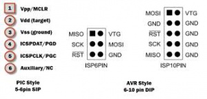
ICSP Pins
In our board, the first pin MOSI is square, the rest are round.
Using Attiny Series Breakout
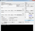
Open avrdudess, and select USBASP and click detect, it will detect your device as shown
