WifiCar
WiFiCar setup
It is not simple to setup the WiFiCar with the provided software. You should have good knowledge of network handling, and Arduino and C programming.
- Install the Arduino IDE (Integrated Development Environment) and the ESP8266 plugin Links #17 for programming the NodeMCU.
- With Arduino IDE upload my program wifi-car-AP.ino (Access Point mode) to the NodeMCU of the car.
- Power Up the NodeMCU, and try to find the WiFi hotspot (name: wifi-car) on IP address 192.168.4.1.
- Upload the provided JavaSript program wifi-carAP.js to the NodeMCU, via the URL http://192.168.4.1/upload (you will be asked for the File name/path).
- With an Android Smartphone connect with WLAN to the WiFicar Hotspot (name: wifi-car).
- Enter in your Web browser the URL http://192.168.4.1 . A HTML file is loaded (embedded in the C program) and the Java script file is loaded and executed.
- As soon, as you tilt the smartphone, the WiFicar will move in that direction.
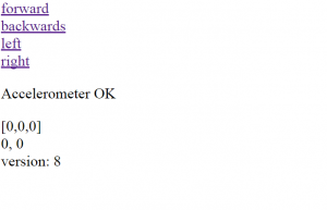
- You should be able to see the interface similar to the right.
Board Pin setup
The WiFi-car signals are also mentioned.
- Main Control Pin
| Functio Description | PWM_A | Motor PWM_B | Dir_A | Dir_B | EN | RST | 3V3 | GND |
|---|---|---|---|---|---|---|---|---|
| NodeMCU Pin | D1 | D2 | D3 | D4 | EN | RST | 3V3 | GND |
| ESP8266 Pin | IO4 | IO5 | IO0 | IO2 | EN | RST | 3V3 | GND |
- On Board Configuration
| Other Pin | VM | A+, A- | B+, B- | VIN |
|---|---|---|---|---|
| Description |
|
Motor Control A | Motor Control B |
|
- Switch and jumper setup
| Configuration | Description |
|---|---|
| Jumper ( VIN->VM<-NC) | Select VIN power for Motor VM power or not |
| Switch (VIN->NodeMCU) | Turn on / off power for control board nodemcu or not |
- Not used Pin
| Lead out pin - digital IO | Lead out pin - analog IO | Lead out pin - digital IO | SPI |
|---|---|---|---|
| D0, D5-D8 | A0, AD | SD2, SD3 | SD1, CMD, SD0, CLK |
| IO16, IO 14,12,13,15 | Analog sampling input, and output (=A0/330*100) | IO9, IO10 | - |
Shield Setup
- Motor power supply (VM): 4.5V ~ 36V, can be powered separately
- Nodemcu Control power (VIN): 4.5V ~ 9V (10VMAX), can be powered separately
- Logic Operating current Iss: ≤60mA (Vi = L), ≤22mA (Vi = H)
- Driver IC: L293, drive = PWM (Pulse Wide Modulation)
- Drive part of the work current Io: ≤1.2A
- Maximum power dissipation: 4W (T = 90 ℃)
- Control signal input level: High: 2.3V≤VIH≤VIN; Low: -0.3V≤VIL≤1.5V
- ESP12E Dev Kit Control Port:
- GPIO0: Motor DirA, Button FLASH; GPIO5: Motor PWMA
- GPIO2: Motor DirB; GPIO4: Motor PWMB
- The screw terminal is labeled with the signal names.
- The push button switch connects VIN to the board.
