WI05 Wifi Module
Introduction
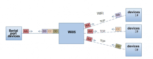
Two-way Wi05 Series Serial to WIFI for packet forwarding, users do not care about the details, the completion of the internal protocol conversion module, serial data port side of the transparent transmission, WIFI network side is TCPIP packets by simply setting, you can set up Web pages inside the module can or also be carried out through the serial port using AT commands, once set up permanent preservation.
WI05 module is an integrated 802.11 b/g/n Wi-Fi, low-power embedded Wi-Fi module, provides a way to connect the user's physical device to a Wi-Fi wireless networks and provide UART interface for data transfer solutions. With this module, the traditional low-end MCU control serial device or devices can easily access Wi-Fi wireless networks, in order to achieve things together network control and management.
The module integrates hardware MAC, baseband chip, RF transceiver unit, and a power amplifier; embedded firmware supports Wi-Fi protocol and configuration, as well as networking, TCP / IP protocol stack.
WI05 using the industry's lowest-power embedded architecture design, and for smart grids, smart application of handheld devices, personal medical, industrial control, etc, these low-flow low-frequency field of data transmission, we did make professional optimization for these fields.
Features
- mono wifi 2.4Ghz, support WEP, WPA/WPA2 security mode
- Price effective MCU design
- fully integrated serial port to wifi wireless function
- Low energy mode available
- support different kinds of network protocol and wifi configuration function
- support STA/AP/STA+AP mode
- support smart link and WPS function
- support wireless and remote upgrading
- internal/external antenna (I-PEX)
- support a few PWM signal output channels
- a lot AT commands configuration supported
- tiny size, 22 x 13.5 x 6 mm
- 3V3 singal power supply
- support low energy realtime OS and driving
- CE/FCC
- ROHS compliant
- UART, 3 PWM/GPIO data port
- current: 200ma on continious working mode (peak), 12ma average mode
- 1x 10 pins, 2.00 pitch
Function
- wireless control
- internet communication
- Data serial communication
Application
- Smart lighting
- Smart power plug
- Industrial control
- remote device surveiliance
- "internal of things"
Use guide
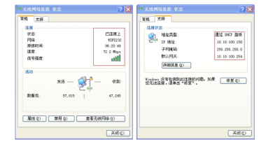
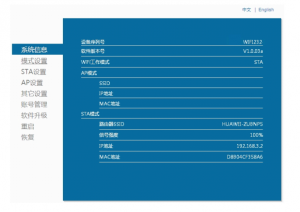
- Connect module via Wifi
- Default settings
SSID: USR-Wifi232
Encrption: open, none;
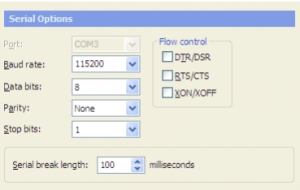
Serial port configuration:115200,8,1,none
TCP/UDP parameters in default: TCP, server, 8899, 10,10,100,254 default login user name and password is "admin" for both
- Pins
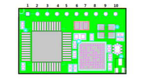
| No. | Name | Description |
|---|---|---|
| 1 | GND | GND |
| 2 | 3V3 | 3v3 Power supply |
| 3 | Reload | factory set pin (hold low for more than 5s), for less than 3s it will enter smart link configuration mode, no need pull-up resistor |
| 4 | Reset | hold more than 10s for reset, need pull-up resistor |
| 5 | RX | Uart RX |
| 6 | TX | Uart Tx |
| 7 | NC | NC |
| 8 | PWM/GPIO/WPS | low to enable WPS function |
| 9 | PWM/GPIO/ready | low to enable, can connect to LED, indicating module working status |
| 10 | PWM/GPIO/link | low to enable, can connect to LED, fast flashing stands for waiting configuration, slow flashing stands for APP enter into smart link mode |
- pin 8, 9, 10 can used as PWM or GPIO function, set AT+LPTIO=on for this function.
- Only use 3V3 for all the logic pins, and 3v3 power pins, higher volt may break the module.
- Hardware features
Module working mode
UART communication mode
- Commands mode (AT)
- To enter into the AT commands mode, type +++ (+ three times), the module will return a confirmation code "a", then type "a" you will have "+ok" return, and now the module enter into AT mode. This commands charachters must enter within 300 ms in between them.
- AT commands list
- enqiry format example, AT+WMODE
- Set format example, AT+WMODE=AP
- Commands end up with <CR> carriage return.
- Can use secureCRT serial tool, default settings as the picture shown below
| Commands | Description | Parameter | Examples(Enquiry/Set) | Category |
|---|---|---|---|---|
| E | turn on/off return message info | - | AT+E | administration |
| WMODE | Check module working mode (AP/STA/AP+STA) | AP, STA, AP+STA | AT+WMODE; AT+WMODE=AP | administration |
| ENTM | enter into data communication mode | - | AT+ENTM | administration |
| TMODE | set/check data mode | throughput: uart data communication, cmd: commands mode, pwm: GPIO mode | AT+TMODE | administration |
| MID | Check module ID | - | AT+MID | administration |
| RELD | return to factory mode | - | AT+RELD | administration |
| Z | Restart module | - | AT+Z | administration |
| H | Help command | - | AT+H | administration |
| CFTGF | copy user configuration to factory configuration | - | AT+CFTGF | administration |
| UART | Check UART settings | AT+UART=baud rate (115200), data bit(8), stop bit (1 or 2), parity (None, even, odd), flow control(NFC, FC) | AT+UART; AT+UART=1200,8,1,NONE,NFC | UART |
| Ping | network command ping | AT+ping=IP address | AT+PING | PING |
| SEND | Send TCP data | AT+send=(data length), enter data to send within 3 seconds after commands | AT+send=10 | Socket A |
| RECV | receive TCP data | AT+recv=(data length), enter data to receive within 3 seconds after commands | AT+recv=10 | Socket A |
| NETP | check/set socket protocol | TCP, UPD | AT+NETP; AT+NETP=UPD, Client, 9090, 10.10.254.22 | Socket A |
| MAXSK | maximum TCP client connected number | 1~5 | AT+MAXSK; AT+MAXSK=10 | socket A |
| TCPLK | check if TCP connection is made | on/off | AT+TCPLK | Socket A |
| TCPTO | check/set TCP time out | unit is seconds | AT+TCPTO; AT+TCPTO=400 | Socket A |
| TCPDIS | set on/off TCP connection | on/off | AT+TCPDIS; AT+TCPDIS=on | Socket A |
| SNDB | Send TCP data via TCP-B | AT+send=(data length), enter data to send within 3 seconds | AT+SNDB; AT+SNDB=10 | Socket B |
| RCVB | receive TCP data via TCP-B | AT+recv=(data length), enter data to receive within 3 seconds | AT+RCVB; AT+RCVB=10 | Socket B |
| SOCKB | check/set socket protocol via TCP-B | TCP, UPD | AT+SOCKB; AT+SOCKB=TCP, 9090, 10.10.254.22 | Socket B |
| TCPLKB | check if TCP connection is made via TCP-B | on/off | AT+TCPLKB | Socket B |
| TCPTOB | check/set TCP time out via TCP-B | - | AT+TCPTOB; AT+TCPTOB=400 | Socket B |
| TCPDISB | set on/off TCP connection via TCP-B | on/off | AT+TCPDISB; AT+ TCPDISB=on | Socket B |
| WSSSID | Check/set associated access point ID SSID | AT+WSSSID; AT+WSSSID=Electrodragon | STA Commands | |
| WSKEY | Check/set encryption parameters | AT+WSKEY=auth(open, shared, WPAPSK, WPA2PSK),encryp(None, WEP-H, WEP-A, TKIP, AES), key | AT+WSKEY; AT+WSKEY=WPA2PSK, TKIP, Electrodragon | STA Commands |
| WANN | Check/set STA parameters | AT+WANN=mode(static,DHCP), address, mask, gateway | AT+WANN; - | STA Commands |
| WSMAC | Check/set MAC parameters | AT+WSMAC=8888 (default value), mac address | AT+WSMAC; AT+WSMAC=8888, D8B0CFFF1234 | STA Commands |
| WSLK | Check/set wireless link status | AT+WSLK | STA Commands | |
| WSCAN | search AP | AT+WSCAN | STA Commands | |
| WSDNS | Check/set DNS address in STA mode | AT+WSDNS; AT+WSDNS=10.10.100.254 | STA Commands | |
| LANN | Check/set AP parameters | AT+LANN=ipaddress, mask | - | AP Commands |
| WAP | Check/set wifi parameters | AT+WAP=wifi mode (11BGN, 11B, 11BG), ssid, channel (only 1 now) | AT+WAP; AT+WAP=11BGN, Electrodrgon, 1 | AP Commands |
| WAKEY | Check/set encryption parameters | AT+WAKEY=auth(open, WPA2PSK),encryp(None, AES), key | AT+WAKEY; AT+WAKEY=WPA2PSK, AES, ELectrdragon | AP Commands |
| WAMAC | Check/set MAC parameters | (DO not use this, please contact us to set otherwise it will cause problems) | AP Commands | |
| WADHCP | Check/set DHCP server status | on/off | AT+WADHCP; AT+WADHCP=on | AP Commands |
| WALK | Check MAC address of connected STAs | - | AT+WALK | AP Commands |
| WALKIND | Check/set connection status | - | AT+WALKIND; AT+WALKIND=on | AP Commands |
| NTPRF | check/set time correction interval | 0~720, unit in minutes | AT+NTPRF; AT+NTPRF=5 | Others |
| NTPEN | turn on/oof tiem correction | - | AT+NTPEN; AT+NTPEN=on | Others |
| NTPTM | check time | - | AT+NTPTM | Others |
| WRMID | Set module ID | - | AT+WRMID=Eletrodragon | Others |
| MDCH | set module wifi auto switch function; on, off, auto, or time interval from 3-120 fro moduel to restart when it has error | - | AT+MDCH; AT+MDCH=Auto | Others |
| TXPWR | set module power level | 0-24, each value equa to -0.5dbm, so 1 equa to -0.5dbm, default 0 is 24 dbm | AT+TXPWR; AT+TXPWR=5 | Others |
| WPS | turn on module WPS function | - | AT+WPS | Others |
| SMTLK | turn on module smart link function | - | AT+SMTLK | Others |
| LPTIO | turn on/off ready, link indication function | on: ready, link, wps functions mapped to pins | AT+LPTIO; AT+LPTIO=on | Others |
GPIO/PWM mode
- Set via At commands AT+ATMODE and AT+LPTIO
- For GPIO mode, set AT+ATMODE=pwm and AT+LPTIO=off, otherwise set link/ready/wps mode AT+ATMODE=AT+ATMODE=pwm, AT+LPTIO=on
GPIO/PWM commands
- GPIO n OUT 0: set GPIO n channel to output mode and low ttl (or 1 for high TTL), return GPIO OK or GPIO NOK
- GPIO n GET: inquiry GPIO n channel pin TTL status, return +ok=1 (or 0) or GPIO NOK
- PWM n frequency duty: set PWM n channel output, return PWM OK or PWM NOK, frequency value 500~60000, duty value 0~100
- PWM n GET: inquiry PWM n channel value, return +ok=frequency or PWM NOK
- PWM n SWT: Save PWM n channel value, return PWM OK or PWM NOK
Features
Module Wifi Mode
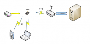
- AP: Wireless access point, you can connect to it like a router
- STA: Wifi station mode, like laptop, PDA is a station
- AP+STA: work as a access point and also a station mode
Encrption
- WEP
- WPA-PSK/TKIP
- WPA-PSK/AES
- WPA-PSK/TKIP
- WPA-PSK/AES
Socket TCP/UDP Communication
- Use tool we have, on this page Wifi
- Connect the moduel, and use the module default setting 10.10.100.254 IP
HTTP Commands
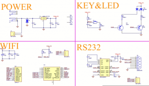
Peripher referenc ecircuit design
