WI04 Wifi Module
Hardware Info
Introduction
The WI04 module provides designers with a ready made component that provides a fully integrated solution for applications, using the IEEE802.11 standard in the 2.4-2.5GHz ISM frequency band, including802.11b/g/n and also provides IEEE802.3, can be quickly and easily included in product designs. The modules integrate all of the RF components required, no need to perform expensive RF design and test. Products can be designed by simply connecting sensors and switches to the module IO pins or uart interface. The modules use ralink’s chip Wireless MCU, allowing designers to make use of the serial interface to connect with their device Hence, this module allows designers to bring wireless applications to market in the minimum time with significantly reduced development effort and cost.
This product is an embedded module based on the universal serial interface network standard,built-in TCP / IP protocol stack, enabling the user serial port, Ethernet, wireless network (wifi) interface between the conversions. Through the WI04 module, the traditional serial devices do not need to change any configuration; data can be transmitted through the Internet network. Provide a quick solution for the user’s serial devices to transfer data via Ethernet Also the Wi04 module have FCC modular approvals and is compliant with EU regulations.
Features
- 2.4GHz 802.11b/g/n,compatible
- Support IEEE 802.3、IEEE 802.3u
- WiFi Client/AP/Router Mode
- Support wps/wds
- The range of baudrate: 1200~500000bps
- Support transparent transmission mode
- Support multiple security authenti-cation
- mechanisms: WEP64/WEP128/ TKIP/ AES / WEP/WPA-PSK/WPA2-PSK
- Support wireless roam
- Support multiple network protocols: PPPOE/TCP/UDP/DDDNS /DHCP/DNS/HTTP/Firewre
- Support AT+ instruction set
- Support two config methods:Serial/WEB
- Device Dimensions 29mm*40mm* 8.8mm
- Lead-free and RoHS compliant
Advantages
- WiFi Router module solutions
- Ready to use in products
- Minimises product development time
- No RF test required for systems
- Compliant with CE and FCC
- Serial to Wifi; Serial to Net; Both by one module
Application
- WiFi Led Control
- WiFi Power Switch
- Home and Commercial building automation
- OBDII WiFi Diagnose
- RFID Data Transfer
- Toys and gaming peripherals
- Industrial systems
- Telemetry
- Remote Control
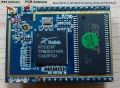
Module Information
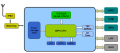
Module diagram
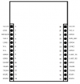
Pin Definitions
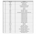
Pin Definitions
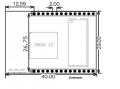
Module Dimension
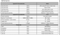
Specification

Electrical characteristics


Reference Design
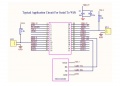
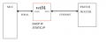
Serial to Wifi, Only use serial to wifi function, no need any RJ45 jack
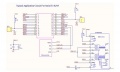
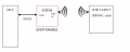
Serial To RJ45, with extra ETH1 RJ45 jack enabled
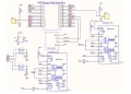
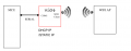
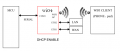
Wireless Router with Serial port(Default Mode) , with extra ETH2 RJ45 jack enabled


Quick Start Manual
- Reset to Factory Settings
To ensure that all the correct configuration process, let the module to restore the factory settings. Mode at the factory module can skip this step. Provide 5V (350mA) power supply to the module is powered up, wait about 30 seconds, start after the completion pulled ES / RST pin exceeds Trst, releasing ES / RST pin, the system will automatically restart. After rebooting the system already in the factory mode.
- Set Working Mode
- Choose either Cable Ethernet or wifi wireless to connect your wi04 board and the target device, for wifi option, you can set the wi04 board to AP or STA (station)
- (Optional)PC set to a static IP mode. IP address of PC set to 192.168.16.100/255.255.255.0, gateway 192.168.16.254.
- Connect through Ethernet (Port Eth2 LAN) or WIFI connection directly. (Wifi ssid default and the default password is 12345678)
- Open in browser: http://192.168.16.254/ser2net.asp, enter into the web configuration page, the default user name password is admin / admin.
- Through web admin the corresponding network parameters. The module ip address is 192.168.16.254.
- TCP/UDP Data Transfer
- Get the TCP test tool from wifi page.
- Set PC on TCP client or TCP server mode, then the wifi module should be vice verse, for UDP, set a pair of client and server as same. This should be done by AT commands (See the ethernet commands below) or at the web console terminal
Functions
Module Working mode
There are four modes for this module
Ethernet
Wifi - Client
Wifi - AP
Default Mode

| Mode | Eth1(WAN) | Eth2(LAN) | Wifi | Ethernet | DHCP/Static |
|---|---|---|---|---|---|
| Ethernet | Yes | Close | Close | Yes | DHCP or Static IP |
| Wifi Client | Close | Close | Yes | Yes | DHCP or Static IP |
| Wifi AP | Close | Close | Yes | Yes (Support all kinds of encryption) | DHCP enable or static |
| Default Mode | Close | Close | Yes | Yes (Support all kinds of encryption) | DHCP enable (default) or static |
Serial Working Mode Switch (Data/AT)
There are two working status of serial port: communication mode and AT mode. When module power up, system will automatically check, if everything goes well, the module will enter into communication mode, otherwise enter into AT commands mode.
There are three ways to enter into At commands mode:
Via ES/RST pin

In any state, maintaining ES / RST pin at low for more than Tes time and less than Trst time, will immediately enter the AT command mode.
Via sending special data during communication

When Serial exit communication function is enabled, you can send specific serial data to the module to exit. Exit serial pass-through process is as follows:
Of which:
Tpt: serial group frame time.
Frame time interval greater than the group continuous transmission of three "+" then wait approximately 500ms (400ms <> 600ms), the time interval greater than the continuous transmission of frames 3 0x1B. Module to exit transparent mode.
Note: This function must exit the serial pass-through feature is turned on in the case in order to use (at + escape = 1 )
Via sending special data during communication 2

Serial exit communication function 2 is enabled, you can send specific serial data 2 to the module exits. Serial eixt the communication process is as follows:
Of which:
Tescape2: specific serial data 2 escape time.
Interval greater than Tescape2 send three "+" module to exit transparent mode.
Note: This function must exit the serial pass-through feature 2222 on the case in order to use (at + escape2 = 1).
Description: The module provides two exits through the serial port communcaiton approach - "specific serial data" and "specific serial data
2". "serial data 2 "is simple, easy to implement, but the data is not strong specificity may cause false triggering." Specific serial data "is relatively complex, but a characteristic strong, less prone to false triggering. Default case, the "specific serial data" is off "specific serial data 2" is enabled.
TCP/UDP Data Transfer Modes
There are four types:
In TCP server mode, the module listen on the specified port, waiting for TCP Client connection, connection, all TCP data is sent directly to the serial port side, sending data to the serial port on all TCP Clien side.
In TCP client mode, the module connect to the specified domain / IP, port. All come from the TCP Server sends the data directly to a serial terminal for the serial port to send data to TCP Server side. Unusual network disconnection could cause the module active reconnect. TCP reconnection function enables active case, TCP Server initiative disconnected, the module will immediately take the initiative to re-connect, otherwise the module will not reconnect.
In UDP server mode, the module opens local port is specified, upon receipt of the data sent to the port, the module will send data to the serial port, and record the remote ip, port. Last connection module will record the information on the remote. Serial data received will be sent directly to the recorded remote ip, port.
In UDP client mode, the module directly to the serial data sent to the specified ip, port. The data returned from the server will be sent to the serial terminal.
Web configuration

You can set the working mode, IP address, etc in the page, the addres is : http://192.168.16.254/ser2net.asp
At Commands List
At commands format:
- at+[command]=[value]\r basic format
- at+remoteip=192.168.11.133\r set thevalue
- at+remoteip=?\r” check the value
- Please see the at commands examples below
| Commands | description | category |
|---|---|---|
| netmode | net working mode | wifi |
| wifi_conf | wifi configration details | wifi |
| channel | wifi channel | wifi |
| dhcpc | DHCP client cong. | wifi |
| net_ip | net ip | wifi |
| net dns | net dns | wifi |
| dhcpd | DHCP server cong. | wifi |
| dhcpd_ip | DHCP server IP | wifi |
| dhcpd_dns | DHCP server DNS | wifi |
| dhcpd_time | DHCP server deploying time | wifi |
| net_commit | submit network changes | wifi |
| out_trans | exit communication | wifi |
| remoteip | remote IP | Ethernet |
| remoteport | remote port | Ethernet |
| remotepro | network protocol | Ethernet |
| timeout | timeout | Ethernet |
| mode | serial uart mode | Serial |
| uart | serial uart cong. | Serial |
| uartpacklen | serial uart pack length | Serial |
| uartpacktimeout | serial uart pack time | Serial |
| escape | escape communication from serial | Serial |
| tpc_auto | TCP auto re-connect | Ethernet |
| save | save serial uart cong. and reboot | Serial |
| reconn | reboot service | General |
| default | reset to default settings | General |
| reboot | reboot module | General |
| ver | check version | General |
| CLport | TCP/UDP client local port | Ethernet |
| RTS | serial output status (485) | Serial |
| XON_XOFF | XON/XOFF traffic control enable | Serial |
| net_wanip | wan ip address | Wifi |
| tcp_client_check | TCP client remote status check | Ethernet |
| S2N_Stat | serial function status | Serial |
| Get_MAC | get MAC address | Wifi |
| wifi_ConState | wifi client connect status | Wifi |
| wifi_Scan | wifi scan | Wifi |
| Suspend | suspend | Gernal |
examples and results return
Gernal Check
- at+netmode=? 0
- at+wifi_conf=? Hi-Link,wpa2_aes,12345678
- at+dhcpd=? 0
- at+dhcpd_ip=? 192.168.14.1,192.168.15.254,255.255.254.0,192.168.15.254
- at+dhcpd_dns=? 192.168.15.254,0.0.0.0
- at+dhcpd_time=? 86400
- at+dhcpc=? 1
- at+net_ip=? 192.168.15.254,255.255.254.0,192.168.11.1
- at+net_dns=? 192.168.11.1,0.0.0.0
- at+net_wanip=? ,,
- at+remoteip=? 192.168.11.245
- at+remoteport=? 8080
- at+remotepro=? tcp
- at+timeout=? 0
- at+mode=? server
- at+uart=? 115200,8,n,1
- at+uartpacklen=? 64
- at+uartpacktimeout=? 10
- at+ver=? V1.39(Dec 6 2012)
Serial to Ethernet Dynamic DHCP (Optional)
- at+netmode=1 ok
- at+dhcpc=1
- at+remoteip=192.168.11.245 ok
- at+remoteport=8080 ok
- at+remotepro=tcp
- at+timeout=0 ok
- at+mode=server
- at+uart=115200,8,n,1 ok
- at+uartpacklen=64 ok
- at+uartpacktimeout=10 ok
- at+net_commit=1
Serial to Ethernet Static IP
- at+netmode=1 ok
- at+dhcpc=0
- at+net_ip=192.168.11.254,255.255.255.0,192.168.11.1 ok
- at+net_dns=192.168.11.1,8.8.8.8 ok
- at+remoteip=192.168.11.245 ok
- at+remoteport=8080 ok
- at+remotepro=tcp
- at+timeout=0 ok
- at+mode=server
- at+uart=115200,8,n,1 ok
- at+uartpacklen=64 ok
- at+uartpacktimeout=10 ok
- at+net_commit=1
Serial to Wifi Client
- at+netmode=2 ok
- at+wifi_conf=HI-LINK,wpa2_aes,12345678 ok
- at+dhcpc=1
- at+remoteip=192.168.11.245 ok
- at+remoteport=8080 ok
- at+remotepro=tcp
- at+timeout=0 ok
- at+mode=server
- at+uart=115200,8,n,1 ok
- at+uartpacklen=64 ok
- at+uartpacktimeout=10 ok
- at+net_commit=1
Serial to Wifi AP
- at+netmode=3 ok
- at+wifi_conf=Hi-Link_,wpa2_aes,0000000000 ok
- at+dhcpd=1 ok
- at+dhcpd_ip=192.168.16.100,192.168.16.200,255.255.255.0,192.168.16.254 ok
- at+dhcpd_dns=192.168.16.254,8.8.8.8 ok
- at+dhcpd_time=86400 ok
- at+net_ip=192.168.16.254,255.255.255.0,192.168.16.254 ok
- at+net_dns=192.168.16.254,8.8.8.8 ok
- at+remoteip=192.168.11.245 ok
- at+remoteport=8080 ok
- at+remotepro=tcp
- at+timeout=0 ok
- at+mode=server
- at+uart=115200,8,n,1 ok
- at+uartpacklen=64 ok
- at+uartpacktimeout=10 ok
- at+net_commit=1
Development Schematic
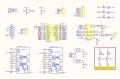
Schematic
Use antenna


FAQ
Can I use it as a wifi hub(repeater)
Yes.
In the default mode, connect the WAN port of WI04 module to the LAN of your modern to get internet into WI04 module
Then you can connect your other device like PC to internet via the LAN port of WI04, or connect via wifi of WI04.