Category:FM
(Redirected from TEA5767 Radio/FM Learning Module (Philips IC))
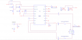
Schematic
- Schematic
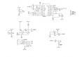
KT0803 Schematic
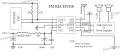
TEA5767 Core Board Schematic
TEA5767 Dev Board Schematic
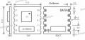
TEA5767 Dimension
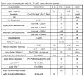
TEA5767 Electrical Charcters
RDA5807M Pin Definition
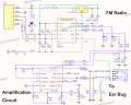
FM1310 64-108MHZ, no MCU
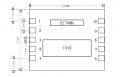
FM1310 Dimension
Other Parameters


Note for FM1310
- C4(0.1UF) has to be close to IC pin 9
- Y1(32.768KHz crystal) has to be close to IC pin 16
- Place an GNDRF parallel next to the RFIN(pin 13) trace, and try to make sure they are the same length.
- L2/L1/L3(Bead) must stay close to the ear bug socket.
- Volumn and seek switch must have separated 100K resistor, can't share this.
Pin Definition
TEA5767 Pin Definition
| Pin | Name | IOs | Description |
|---|---|---|---|
| 1 | Data | I/O | IIC Data Line |
| 2 | Clock | I | IIC Clock Line |
| 3 | GND | - | Gound |
| 4 | NC | - | NC |
| 5 | VCC | - | Voltage supply |
| 6 | GND | - | Gound |
| 7 | L-OUT | O | Audio left channel output |
| 8 | R-OUT | O | Audio right channel output |
| 9 | GND | - | Gound |
| 10 | ANT | I | RF Antenna |
RDA5807 Pin Definition
| Pin | Name | Description |
|---|---|---|
| 1 | GND | GND |
| 2 | R-out | right sound channel signal output |
| 3 | L-out | left sound channel signal output |
| 4 | RCK | External clock input |
| 5 | FM | FM antenna |
| 6 | Data | IIC SDA Data Line |
| 7 | Clock | IIC SCL Clock line |
| 8 | GP2 | NC |
| 9 | GP3 | NC |
| 10 | VDD | +3VDC input |
FM 1310
- Absolute Maxiumium ratings
| Item | Min. | Max. |
|---|---|---|
| Power Supply Volts VCC | –0.3V | 3.6V |
| Pin Voltage | –0.3V | 3.6V |
| Maxium power dissipation | - | 1W |
| Operating temperature | –40C | +85C |
| Storage temperature | -65C | +150C |
| LNA input level | - | +10 dBm |
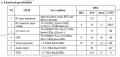
- Electric Characters
| Item | Symbol | Min. | Typ. | Max. | Unit |
|---|---|---|---|---|---|
| Supply Voltage | VCC | 2.2 | 3.6 | V | |
| Total Supply Current | I_A | 15.8 | mA | ||
| Total Power Down Current | I_PDA | 16 | uA |
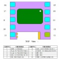
- Pin Definition
| Pin Number | Name | Description | Remark |
|---|---|---|---|
| 1 | FM_ANT | FM Antenna signal input | |
| 2 | GND | power ground | |
| 3 | Seek_D | seek channel down | connect with a switch and 100K resistor to VCC |
| 4 | Seek_U | seek channel up | Connect a siwtch to GND |
| 5 | Vol_D | volumn down | connect with a switch and 100K resistor to VCC |
| 6 | Vol_U | volumn up | Connect a siwtch to GND |
| 7 | On | module enable ON | |
| 8 | Vbat | Power VCC | normally 3V |
| 9 | Rout | stereo audio right channel | |
| 10 | Lout | stereo audio left channel |
Documents
Datasheet
KT0803
TEA5767
RDA5807M
Tutorial
http://www.instructables.com/id/TEA5767-FM-Radio-Breakout-Board-for-Arduino/
http://www.doctormonk.com/2012/03/tea5767-fm-radio-breakout-board-for.html
http://kalum.posterous.com/arduino-with-tea5767-single-chip-radio-and-no
This category currently contains no pages or media.