Stackable Bluetooth BT Arduino Shield
Introduction

Bluetooth Shield a serial port Bluetooth module (Master/Slave) breakout board. You can choose ARDUINO's Digital PIN D0->D7 as Software UART to communicate with Bluetooth Shield(and D0,D1 also is Hardware UART).
There is a HC-05 on the board and it's an easy to use Bluetooth SPP module designed for transparent wireless serial connection setup.
It can be configured to Master, Slave or Loopback three different modes, and it will connect to or be connected by other devices that support SPP protocol per configuration, and it is a suitable substitute for most applications.
Feature
- Hardware Features
- Arduino compatible.
- Typical -80dBm sensitivity.
- Up to +4dBm RF transmit power.
- Fully Qualified Bluetooth V2.0+EDR 3Mbps Modulation.
- Low Power Operation.
- PIO control.
- UART interface with programmable baud rate.
- Integrated PCB antenna.
- Software Features
- Default Baud rate: 38400, Data bits:8, Stop bit:1,Parity:No parity.
- Supported baud rate: 9600,19200,38400,57600,115200,230400,460800.
- Status instruction port PIO1: low-disconnected, high-connected(3V3);
- Auto-connect the last device on power as default.
- Permit matched device connect by default.
- Default PINCODE:”1234”.
- Auto-reconnect in 30 min when disconnected as a result of beyond the range of connection.
Cautions
- Only between master device and slave device can be paired with each other. Between Master and Master devices or Slave and Slave devices can't be paired each other. The Slave mode could be paired with PDA, PC etc.
- Make sure your main board IO is 3.3V
Board Setup

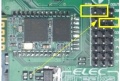
Note: The switch is not for 3.3V/5V power supply, but be used with jumper cap for HC-05 to enter AT mode. Three kinds of match:
Case 1: The cap jump to 'SW'(switch) and switch at 'H' side that means input high level to the Bluetooth HC-05's PIN34. Then the module will enter to AT mode.
Case 2: The cap jump to 'SW'(switch) and switch at 'L' side that means quit AT mode.
Case 3: The cap jump to 'I/O' and whatever switch side, that means you can control the level of PIN34 by Arduino's D6 pin and control when enter AT mode.

Usage
How could I sent the command to Blueooth Shield module ?
First, you need enter AT mode in accordance with the above method. Then, there are three ways use Serial port send command to Bluetooth Shield. Detail option please reference to post communication between Android and Arduino with Bluetooth.
Case 1. Direct connect to Arduino main board Serial port, DIN to RX_H(D0) , DOUT to TX_H(D1) but it need you remove the MCU chip.
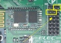
Case 2. Setting the Bluetooth shield’s jumper connect: DIN to TX_H(D1) , DOUT to RX_H(D0). So this way just for you has perfect code and don’t need monitor from serial port, because you cann’t see anything from serial port tool.
Case 3. use Software Serial library to define D2 and D3(Of course others) as a virtual serial port TX and RX. By this way, you can use Arduino’s Serial Monitor to Monitor operation of the code.


Programming
Usually we used software Serialport library to control and communication with Bluetooth Module. The Preparation steps:
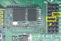
Step One: Hardware connect
Use the Case 3 connection. And we jumper cap to SW side and set switch to H side. Then use Software Serial library to define D2 and D3(Of course others) as a virtual serial port TX and RX. By this way, you can use Arduino’s Serial Monitor to Monitor operation of the code.
Step two: Software control
First of all, you need a software library. There we used NewSoftSerial library. Get it from here
Put the library to : ...\your_ArduinoIDE_Path\arduino-0022\libraries
Copy below demo code and run. This just a sample code for your reference and you can modified and change it whatever you want.
Step Three: AT command
Now, You can send AT commanD from Serial port to control and setting the Bluetooth module. And you can set the module to Master or Slave......
You can play with Master mode to send paired require to others Bluetooth devices or Slave mode to wait others Bluetooth devices discover.
Includes important code snippet. Demo code like :


#include <NewSoftSerial.h>
#include <TimerOne.h>

#define rxPin 2
#define txPin 3

NewSoftSerial mySerial(rxPin, txPin);

void Callback()
{
   Serial.println("------->  Callback Send AT");
   mySerial.print("AT\r\n");
}

void setup()
{
   // define pin modes for tx, rx pins:
   pinMode(rxPin, INPUT);
   pinMode(txPin, OUTPUT);
   mySerial.begin(38400);
   Serial.begin(38400);

   //Timer1.initialize(2000000);             // setting callback is 2s
   //Timer1.attachInterrupt(Callback);
}

void loop()
{
  int i = 0;
  char someChar[32] = {0};
  // when characters arrive over the serial port...
  if(Serial.available()) {
    do{
      someChar[i++] = Serial.read();
      //As data trickles in from your serial port you are grabbing as much as you can,
      //but then when it runs out (as it will after a few bytes because the processor
      //is much faster than a 9600 baud device) you exit loop, which then restarts,
      //and resets i to zero, and someChar to an empty array.So please be sure to keep this delay
      delay(3);

    }while (Serial.available() > 0);

    mySerial.println(someChar);
    Serial.println(someChar);
  }

  while(mySerial.available())
      Serial.print((char)mySerial.read());
}
Note for arduino Mega
If you used Arduino Mage1280/250 there are some different.Please note the NewSoftSerial library about Mage2560 explanation in SoftwareSerial.cpp :
// Specifically for the Arduino Mega 2560 (or 1280 on the original Arduino Mega)
// A majority of the pins are NOT PCINTs, SO BE WARNED (i.e. you cannot use them as receive pins)
// Only pins available for RECEIVE (TRANSMIT can be on any pin):
// (I've deliberately left out pin mapping to the Hardware USARTs - seems senseless to me)
// Pins: 10, 11, 12, 13,  50, 51, 52, 53,  62, 63, 64, 65, 66, 67, 68, 69
That's mean the library do not support D0-D7 as receive pins, just could use pins:10, 11, 12, 13, 50, 51, 52, 53, 62, 63, 64, 65, 66, 67, 68, 69 for receive. So there are two way to resolve it, but all need external jumper wires.
First method: Change the define of rxPin and txPin. Jumper wires connect DOUT-D10, DIN-D11.
#define rxPin 10
#define txPin 11
Second method: Use the others Hardware Serialport because of Mage there are 4 hardware serialport. Jumper wires connect DOUT-RX1(D19) DIN-TX1(D18)
The below demo is second method:


void setup()
{
   Serial.begin(57600);
   Serial1.begin(38400);

}

void loop()
{
  int i = 0;
  char someChar[32] = {0};
  // when characters arrive over the serial port...
  if(Serial.available()) {
    Serial.print("------->  ");
    do{
      someChar[i++] = Serial.read();
      //As data trickles in from your serial port you are grabbing as much as you can,
      //but then when it runs out (as it will after a few bytes because the processor
      //is much faster than a 9600 baud device) you exit loop, which then restarts,
      //and resets i to zero, and someChar to an empty array.So please be sure to keep this delay
      delay(3);
    }while (Serial.available() > 0);
    Serial1.println(someChar);
    Serial.println(someChar);
  }

  while(Serial1.available())
      Serial.print((char)Serial1.read());
}
FAQ
- Why pair failed and quit when I use at+role=0 mode and APK with 'AS Client' mode ?
when I selected 'HC-05' in pair list after search Bluetooth devices on APK, but not display pairing dialog and then APK quit 'AS Client' menu to Main menu.
So I check the Java APK and found the reason is paired failed. After then I reset pair list, I can pair successful and communication again.
The step is:
- at+cmode=1 // connect the module to any address (The specifying address has no effect for this mode.)
- at+adcn // return 1 that means there is 1 authenticated device in the pair list. So we need clear it
- at+rmaad // Delete all authenticated devices in the pair list
- at+adcn // return 0 that means there is 0 authenticated device in the pair list. that's right now.
Then power down the Bluetooth Shield more then 2 minutes, beause of mostly of Android phone the default paire time is 2 minutes.
After more then 2 minutes, you can pair with Bluetooth Shield again, and this time there will show pairing dialog, input '1234' . Once you
paired successful, the led2 will light which near SWITCH.
