SIM900 GSM/GPRS Shield (for Arduino)
Pins Definition
| Interface | Pin | Description |
|---|---|---|
| GPIOs | 1 | VDD * |
| GPIOs | 2 | GND |
| GPIOs | 3 | GPIO1 |
| GPIOs | 4 | GPIO2 |
| GPIOs | 5 | GPIO3 |
| GPIOs | 6 | GPIO4 |
| GPIOs | 7 | GPIO5 |
| GPIOs | 8 | GPIO6 |
| GPIOs | 9 | GPIO7 |
| GPIOs | 10 | GPIO8 |
| GPIOs | 11 | GPIO9 |
| GPIOs | 12 | GPIO10 |
| GPIOs | 13 | GPIO11 |
| GPIOs | 14 | GPIO12 |
| GPIOs | 15 | GND |
| GPIOs | 16 | VDD* |
| UART | 1 | GND |
| UART | 2 | DTR |
| UART | 3 | RI |
| UART | 4 | DCD |
| UART | 5 | CTS |
| UART | 6 | RTS |
| UART | 7 | TXD |
| UART | 8 | RXD |
| IIC&PWM | 1 | GND |
| IIC&PWM | 2 | GND |
| IIC&PWM | 3 | IIC_SCL |
| IIC&PWM | 4 | IIC_SDA |
| IIC&PWM | 5 | PWM2 |
| IIC&PWM | 6 | PWM1 |
| IIC&PWM | 7 | GND |
| IIC&PWM | 8 | GND |
| Debug_Port | 1 | GND |
| Debug_Port | 2 | PERKEY |
| Debug_Port | 3 | DBG_RXD |
| Debug_Port | 4 | DBG_TXD |
VDD* = 3.0V
Note 1: the operation level of the port is 3.0V
Installation
Com Switch
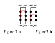
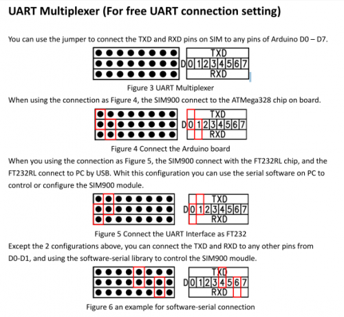
There is a com switch for selecting the communicate port to UART port or Debug port of SIM900 module as the following figure 7. When connect to the SIM900 debug port, the UART multiplexer just can be set as Figure 4 or 5.

RI Behavior Output
There is a Jumper for configuration of RI, one to connect D3, another to connect D14.
| Status | RI response |
|---|---|
| Standby | High |
| Voice call | The pin is changed to low. When any of the following events occur, the pin will be changed to high: (1) Establish the call |
| Data call | The pin is changed to low. When any of the following events occur, the pin will be changed to high: (3) Establish the call |
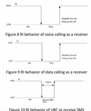
| SMS | The pin is changed to low, and kept low for 120ms when a SMS is received. Then it is changed to high. |
| URC | The pin is changed to low, and kept low for 120ms when some URCs are reported. Then it is changed to high. |
The behavior of the RI pin is shown in the following figure when SIM900 module is used as a receiver.

When the module is used as caller, the RI will remain high.
Indicator LED and Buttons:
NETSTATUS: The status of the NETSTATUS LED is listed in following table:
| Status | Description |
|---|---|
| Off | SIM900 is not running |
| 64ms On/800ms Off | SIM900 not registered the network |
| 64ms On/3000ms Off | SIM900 registered to the network |
| 64ms On/300ms Off | GPRS communication is established |
- STATUS: Power status of SIM900.
- PWR: Power status of IComSat.
- SIM900-POWER: After the IComSat power on, you need to press the SIM900-POWER button for a
- moment to power on the SIM900 module.
- Sim900-RST: Reset the SIM900
- Arduino-RST: Reset the Arduino.
