Regular GPIO Mapping
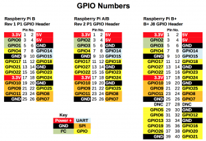
- The following GPIO use should be set in python RPi.GPIO, by GPIO.BCM, image refer to here.
| GPIO.BOARD |
GPIO.BCM |
on-board GPIO marking pin |
Arduino pin
|
| 11 |
GPIO17 |
RPI_0 |
D2
|
| 12 |
GPIO18 |
RPI_1 |
D3
|
| 13 |
GPIO27 |
RPI_2 |
D4
|
| 15 |
GPIO22 |
RPI_3 |
D5
|
| 16 |
GPIO23 |
RPI_4 |
D6
|
| 18 |
GPIO24 |
RPI_5 |
D7
|
| 22 |
GPIO25 |
RPI_6 |
D8
|
| 7 |
GPIO4 |
RPI_7 |
D9
|
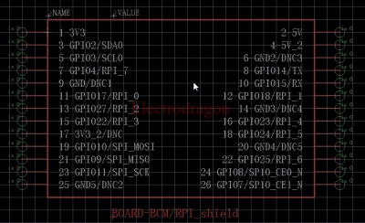
- Also can referring to following image. 7-GPIO4/RPI_7 means: for GPIO.BOARD number is 7, for GPIO.BCM number is 4, and for our GPIO shield number is 7

Using with 5110 LCD by wiring PI
- Make sure you have wiringPi installed.
- Navigate to the demo code folder, open the make file you will see the following content:
- Compile code by wiringPi:
gcc -g -o lcd5110 PCD8544.c pcd8544_rpi.c -lwiringPi
- run make command and then run ./lcd5110 as an executable file.
Wiring
| 5110 |
Raspberry Pi
|
| VCC |
3V3 or 5V
|
| LED (BL) |
3V3
|
| GND |
GND
|
| RST |
D6 (GPIO4)
|
| CE |
D5 (GPIO3)
|
| DC |
D4 (GPIO2)
|
| DIN |
D3 (GPIO1)
|
| SCK |
D2 (GPIO0)
|
Documents

