ProgBee UART Programmer (Xbee Supported)
- Key Specifications
| Microprocessor | FT232RL |
|---|---|
| PCB size | 3.1cm x 4.1cm |
| Indicators | POWER,Green LED. LEDs for Txd and Rxd |
| Power supply | 3.3V and 5V DC |
| Interface | Mini-B USB, 2.54mm pitch pin header |
| Adapter socket | XBee compatible 2.0mm pitch female pin header |
| Connectivity | USB |
| Communication Protocol | UART, Bit Bang I/O, SPI |
| ROHS | YES |
- Electrical Characterstics
| Specification | Minimum | Typical | Maximum | Unit |
|---|---|---|---|---|
| Input voltage | - | 5 | 5 | Vdc |
| Current Consumption | - | - | 500 | mA |
| Output voltage | 3.3 | - | 5 | Vdc |
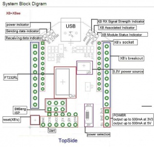
- A tiny reset switch is provided for reseting Bee compatible devices.
- Apart from 2 x 10 Breakout for BEE compatible modules, additional pads for 2 x 10pin headers, 2 x 3 ISP header are provided.Users can solder pin headers appropriately.
BitBang Mode
An nice feature of UartSBee v3.1 compared to other FT232RL based USB-Serial devices is that all the Bit-Bang I/Os are brought to the header pins.
Bit-Bang mode is a special feature of FT232RL in which 8 I/O lines (D0 - D7) can be used as a general purpose bidirectional I/O lines. Three Bit-Bang modes are supported by FT232RL
- Asynchronous Bit-Bang mode
Any data written to the device is clocked to the configured output pins. The rate of data transfer is configured based on baud rate generator. In this mode any of 8 I/O lines can be configured as input or ouput.
- Synchronous Bit-Bang mode
In this mode data is sent synchronously. An input is read before an output byte is sent to the device. Hence to read input, a write operation must be performed.
- CBUS Bit-Bang Mode
This is a special mode which requires reprogramming of FT232RL EEPROM. This uses signals C0 - C3.
Bit-Bang Mode of FT232RL is well documented in the application note[1]
Table: Bit-Bang I/O Mapping
| UartSBee Signal | BitBang I/O Signal |
|---|---|
| TxD | D0 |
| RxD | D1 |
| RTS | D2 |
| CTS | D3 |
| DTR | D4 |
| DSR | D5 |
| DCD | D6 |
| RI | D7 |
Documents
- See FTDI on this page.

