Portable Digital Oscilloscope DSO201 Nano V1
Introduction
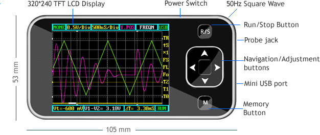
DSO nano is a pocket size digital storage oscilloscope fulfills basic electronic engineering requirements. It is base on ARM Cortex™-M3 compatible 32 bit platform, equipped with 320*240 color display, SD card capability, USB connection, and chargeable batteries. Weighs only 60g.
Features
- Super portable and lightweight
- 2.8” color 320*240 display
- Micro SD card Waveform Storage
- Basic 1Msps sample rate with 12bit resolution
- Various measurement markers
- Various trigger mode
- Build-in test signal
- USB chargeable battery
- Open source
User Interface
Specification
May include key specification and other specifications.
Key Specification
| Display | 2.8″ Color TFT LCD |
| Display Resolution | 320×240 |
| Display Color | 65K |
| Analog bandwidth | 0 - 200KHz |
| Max sample rate | 1Msps 12Bits |
| Sample memory depth | 4096 Point |
| Horizontal sensitivity | 1uS/Div~10S/Div (1-2-5 Step) |
| Horizontal position | adjustable with indicator |
| Vertical sensitivity | 10mV/Div~10V/Div (with ×1 probe) 0.5V/Div~100V/Div (with ×10 probe) |
| Vertical position | adjustable with indicator |
| Input impedance | >500KΩ |
| Max input voltage | 80Vpp (by ×1 probe) |
| Coupling | DC |
| Trig modes | Auto, Norma, Single, None and Scan |
| Functionalities: | Automatic measurement:
|
| Test signal | Built-in 10Hz~1MHz (1-2-5 Step) |
| Waveform storage | SD card |
| PC connection via USB | as SD card reader |
| Upgrade | by bootloader via USB |
| Power supply | 3.7V Chargeable Lithium battery / USB |
| Dimension (w/o probe) | 105mm X 53mm X 8mm |
Application
The Pocket Oscilloscope applies to the following occasions:
- Go out for repairing electronic equipment (air conditioning or industrial frequency power conversion, AC / DC switching power supply or inverter, elevator and building fire-fighting equipment, industrial control circuit)
- Hardware maintenance or software debugging RS232, RS485, I2C, CAN and other communications interface circuits, LED display and keyboard scan driver circuit, brushless motor drive circuit.
- Audio equipment and circuits, electronic toys and remote control models, car repair electronic circuits.
- Educational teaching practice and student development of electronic small production.
- Need to slow signal changes observed applications (such as: relay and switch contacts jitter, battery charge and discharge curves, power supply load transient response characteristics of the temperature sensor measurements)
- Power supply of the electronic circuit (SCR voltage regulator, power factor compensation, electronic energy saving lamps, dysprosium lamp mercury lamp sodium lamp drive circuit xenon lights, etc.)
- As for other things like: CPU clock, RAM access, bus and USB or Ethernet signal measurement, high frequency and the video circuitry and the need to use the FFT signal analysis and so on occasion, 700 USD oscilloscopes often not necessarily competent, recommendations or buy high-end oscilloscope it!
Usage
Basic Usage
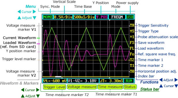
The UI could be divided to 4 parts: main menu (top), functions (right column), status bar (bottom), and waveform & markers displays. Use cursor up , down, left , right to navigate among the three operational parts and make adjustments.
Waveform & Markers
- Green waveform - current signal being monitored
- Purple waveform – reference waveform loaded from SD card.
Page 4 of 9 10/26/2009
- Voltage measure marker V1 and V2 (Dot, vertical) – A voltage measure value between
V1-V2 could be displayed.
- Time measure marker A and B (Dot line, horizontal) – A time measure value between A
and B could be displayed.
- Y positions marker (Purple) – Y position center line for adjustment reference
- Trigger level marker (Yellow) – Used to set trigger level
Menu
Horizontal main menu on top of screen, Navigate by left and right, adjust by up and down. Sync. Mode: When blinking, press up and down to select 4 different synchronization mode: AUTO, NORM, SING, and NONE.
- AUTO – Automatic synchronous sweeping mode, displays waveform even not
triggered.
- NORM – Normal synchronous sweeping mode, displays whenever trigged.
- SING- Single sweeping mode, display when triggered, then stopped with latest
triggered waveform.
- NONE – Random sampling mode
- SCAN – Scan mode, to check long period low frequency signal.
Vertical Scale: When blinking, press up and down to select different level of sensitivity. Total 19 scales are optional from 10mV/Div to 100V/Div.
- Note 1: If you use scale above
20V/Div, please use probe with attenuation of 10:1).
- Note 2: If newly set scale does not
match reference waveform, the latter will be cleared.
Horizontal sensitivity: When blinking, press up and down to select different sensitivities. from 1uS/Div to 10S/Div total 22 grades. Note 2: If newly set sensitivity does not match reference waveform, the latter will be cleared.
Y position: When blinking, press up and down to adjust the vertical position of the waveform. Press M to hide/activate Y position marker if needed.
Calculation Mode: Auto calculation modes include:
- FREQN – Signal frequency
- CYCLE – Signal period
- DUTY – Duty time
- Vpp – AC signal peak-peak value
- Vram – AC signal effective value
- Vavg – AC signal average value
- DC.V – DC signal average value.
Power supply mode: Power supply by internal battery or USB port. Battery bar will be displayed when powered from internal.
Functions
Vertical function buttons on side of screen, Navigate by up and down ,adjust by left and right.
Trigger sensitivity: When blinking, press left and right to adjust trigger sensitivity, trigger level marker (Yellow dotted area) changes correspondingly.
Trigger Type: When blinking, press left and right to choose trigger mode of rising edge or falling edge.
Probe attenuation scale: When blinking, press left and right to choose 1:1 or 1:10 probe.
Save waveform: When blinking, status bar will display “ Save Filexxx”, press left and right to select file name with xxx = 000-255. Press M to save current waveform on display to SD card.
Load waveform: When blinking, status bar will display “ Save Filexxx”, press left and right to select file name with xxx = 000-255. Press M to load current waveform to display from SD card.
Note: current version has no file creation function, a FILEXXX.DAT must be prepared by connecting to PC by USB.
Ref. square wave freq: When blinking, press left and right to adjust the frequency of reference square wave.
Horizontal position adj: When blinking, press left and right to scroll waveform horizontally.
Index Bar: Show current display position of total loaded wavefrom.
Status Bar
Time markers: When blinking, press left and right to adjust T1 or T2 time measure marker, the time difference PT=T1-T2 will be displayed.
Voltage markers: When blinking, press left and right to adjust V1 or V2 time measure marker, the Voltage difference PV=V1-V2 will be displayed.
Trigger level: When blinking, press left and right to adjust trigger level, trigger level marker (Yellow dotted line) changes correspondingly.
Save Settings
Hold “R/S” Button and press “M” button to save current settings as default.
Firmware and upgrades
The DSO Nano v1 can use the same firmware as v2. See the common DSO Nano page for more information.
Bill of Materials (BOM) /parts list
Package list
- DSO nano body x 1
- 3.7v lithium battery with connector x 1
- Back plate x 1
- Mini Probe x 1
- Manual X1
- Protection bag X1
FAQ
Question1: What is the maximum input voltage when using a 10x probe on the Nano DSO?
Answer: The maximum input voltage could be 80Vpp. So when using a 10x probe on the Nano DSO, it could be 800 Vpp. However, we did not test that, and we are not responsible for any damage and injury because of measuring high voltage.
Resources
How to buy
Other Note
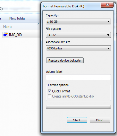
Setup your SD card for first time usage:
- Format SD card like the setting below, it should works, the card capacity should be no more than 2GB:


