Parola
Chained Dot Matrix Display Parola
Installation Steps (Simple)
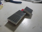
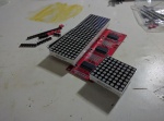
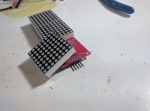
- Take 3-set matrix display for example
Soldering Step by Step (Complex)
| Step | Note | Header text |
|---|---|---|
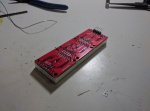
| 1 | Soldering 4 pcs of 2x5 pin header of the back side of PCB | carefully do not block the pin holes of the dot matrix during soldering, since they are very close, prepare desoldering tool in case |
| 2 (optional) | Soldering the dot matrix socket pin header 1x8 | This is optional, if you prefer a slim display chain, and no need to remove the dot matrix anymore |
| 3 | place dot matrix on the socket, or soldering directly on board | be VERY carefully if you solder it directly on board, the direction of the dot matrix should not be wrong , otherwise it will be useless board |
| 4 | Add jumpers on 2x5 pin headers, add signal or right of your chain display, should work now! | try with MAX_72XX -> test sketch in arduino |
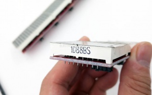
- The dot matrix has a "dot" or print words on the side of its left, "the left side of the IC"
- The right angle pin header should be soldered on the right, "the right side of the IC"
Software
- use library and demo code from here: https://github.com/Edragon/Arduino-main/tree/master/libraries/MD_MAX72XX
Wiring
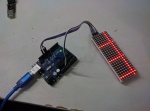
- Connect to the right side pins of matrix (design error, both side marked with DOUT, but right side (when you face to the matrix) should be DIN)
- Find follwing part and setup in Arduino, max72xx test sketch:
#define	MAX_DEVICES	5 // how many you chained
#define	CLK_PIN		13  // or SCK - CLK
#define	DATA_PIN	11  // or MOSI - DIN
#define	CS_PIN		10  // or SS - LD (load)
Library and Demo code
- Tested on arduino IDE version 1.67
- Download MAX_72XX and true random library from our dropbox page or github here and true random here.
- Now you can run Max_72xx_text example to test it.
- Then find the parola demo code here. or from our dropbox page.
Documents
Demo video
- Demo Video 1 based on parola example
- Demo Video 2 based on library max_72xx_test example
- Color Dot Matrix
