HP25 LED Panel
SKU ILE1073
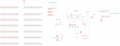
Pin Definitions
| Arduino | Header text | PIN Left | PIN Right | Header text | Arduino |
|---|---|---|---|---|---|
| - | VCC | 1 | 8 | GND | - |
| 0 | IR | 2 | 7 | LED | 4 |
| 1 | BTN | 3 | 6 | UPDI | 5, PROG |
| 2, PA1 | TXD | 4 | 5 | GND_detect | 3, RX_PA2 |
Arduino Definitions
#define IR 0
#define BTN 1
#define GND_detect 3
#define LED 4
Programming Setup TX/RX to pin PA1 and PA2
- Arduino pin reference please see here: https://github.com/SpenceKonde/megaTinyCore/blob/master/megaavr/extras/ATtiny_x02.md
Programming
- Prepare Arduino Nano UPDI programmer
- Connect UPDI, VCC and GND three lines
- upload code by "uploading using programmer", and select programmer "jtag2updi"
Power supply
- Power supply can be attached from B+ | B-, or SO+ | SO-, if you use solar panel better applied at SO+|SO-
- Power supply up to 30V DC
- For lower than 5V, you can shot connect the pads next to the LDO, to supply power directly to LEDs
Schematic
Schematic