EDGPU1 Basic
Basic
- Display show the welcome interface
- User send commands in 10 seconds after power up to enter serial mode
- Connect with serial USB-TTL tool, like CP2102, FT232RL, HX2303TA, CH340 etc.
- Busy - to check if commands still running, you can use delay function of MCU is fully enough
- Upgrade - short connect 3.3V+BOOT
Font
- Self-contained Chinese character library, support 12,16 dot matrix GB2312 (GB2312) all Chinese characters and 24,32,48,64 dot matrix small characters Chinese characters (SCCC) and characters, each size of the small font can store 512 characters and characters, but all small fonts are not allowed Speak super 384K length
- Memory space allows the case, allowing 24,32,48 dot matrix full font display (FF), easy to display display names and other special display applications
- Serial transmission data non-binary coding, but the use of statement mode, to facilitate human reading, display Chinese characters can be directly transmitted Chinese characters string, no need to change the number, easy to read and debug;
- Serial command buffer 1024 bytes, to facilitate a large number of display statements, increase the UI effect;
Image and drawing
- Support points, lines, caught, box, fill box and other basic graphics display;
- Support graphics display, the maximum allowable 512 graphics, but the total length can not exceed 1M bytes (each figure accounted for: long * wide * 2)
- Support ICON class, automatically intercept part of the entire picture display (by the same size ICON composition of the large map mode) to support the picture of the crop display (cut display)
- Support background and Chinese characters overlay display (12 dot matrix does not support)
Touch screen technical parameters
- Supports 3 modes: drawing mode, dot matrix mode and hot zone mode
- Hot zone mode to support hidden hot area, thin wire frame, thick frame, thin line convex and concave button and thick line convex and concave button and cut the map, a total of 6 modes, and can customize the color, hot zone click to respond
- Internal integrated touch screen calibration interface, can be easily called
- Each screen supports 32 hot areas, you can easily create a numeric keypad
- Hot zone number outgoing, easy programming;
Get Started Guide
Basic: Using with USB-TTL (CP2102)
- solder pin header for connection 5V, GND, TX RX to CP2102
- solder AMS1117 on board as a 5V-3.3V power regulator
- Connect, and download GUI tool below
- Click auto connect, double check wiring, system will show connect to EDGPU
- Upload code -> start sync
Using with Arduino
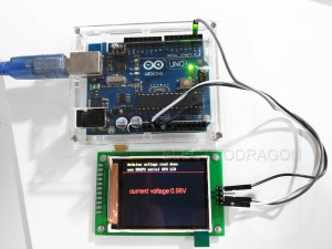
- Design a simple analog voltage read
- Connect the EDGPU board with three lines: 5V-5V, GND-GND as power trial, and arduino tx to EDGPU rx. Only need three lines
- Create the string line file in notepad in windows:
const char hz[][32]={  // this line declare a char of 32 bytes
    "current voltage:",	//0-
    "Arduino voltage read demo",	//1
    "use EDGPU serial GPU LCD",	//2
};
- "save as" in the save screen, make sure choose decode type is "ANSI" NOT else, save is as ed.c file
- Main program file:
#include"e:\arduino\Udemo\ed.c" // include the file just created above, please check the directly accordingly
void setup() {
  Serial.begin(115200);
   while (!Serial) {
    // wait for serial line to be ready
  }
  Serial.print("CLS(0);");

  Serial.print("DS16(20,2,'");  // DS16 line
  Serial.print(hz[1]);
  Serial.print("',4);");

  Serial.print("DS16(20,22,'");
  Serial.print(hz[2]);
  Serial.print("',15);");

  Serial.println("PL(0,40,399,40,1);"); // must be println at end
  Serial.flush(); // this is optional
  delay(200);  // must have delay

}

// the loop routine runs over and over again forever:

void loop() {
  // read the input on analog pin 0:
  int sensorValue = analogRead(A0);
  float vol=sensorValue*2.5/1024; // this is only demonstration only.

  Serial.print("DS24(30,100,'"); //DS24 line
  Serial.print(hz[0]);
  Serial.print(vol,2);   // print float type with two digitals
  Serial.println("V',1);");
  delay(150);        // delay in between reads for stability
}
- upload
