Category:LD3320
Function Map, Pin Definition
Documentation:
Demo Code
Demo Code MSC-51
LQ_LD3320onlyASR
LQ_LD3320onlyMP3
LQ_LD3320testUV2
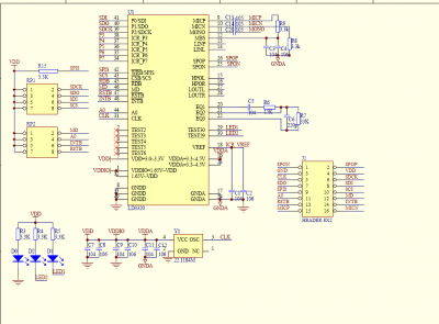
Pin Definition
| Pin Name | Description | For SPI | Pins in Demo | Pin Name | Description | For SPI | Pins in Demo |
|---|---|---|---|---|---|---|---|
| SPON | Speaker Output Negative | NC | - | SPOP | Speaker Output Positive | NC | - |
| GND | GND | GND | GND | 3.3V | 3.3V | 3.3V | 3.3V |
| CLK | Clock Input | Yes, can shared crystal with MCU | - | SDCK | Parallel bit-1 | SPI Clock | P0^0 |
| SDO | Parallel bit-7 | SPI Data output | P0^6 | SDI | Parallel bit-0 | SPI data input | P0^1 |
| SPIS | Parallel write | SPI Enable, can directly to GND | P0^5 | CSC | Parallel Chip Select | SPI Chip Select | P0^2 |
| A0 | Address or Data Select | NC | - | MD | Mode Select (0=parallel, 1=SPI) | - | P0^4, or to VCC |
| RSTB | reset input (Enable on low) | - | P0^3 | INTB | Interrupt (Enable on low) | - | P3^2 |
| MICP | Microphone input Positive | - | To microphone | MICN | Microphone input Negative | - | To microphone |
Schematic
All the following demo code works with STC 51MCU
Pages in category "LD3320"
The following 3 pages are in this category, out of 3 total.
Media in category "LD3320"
This category contains only the following file.
- LD3320 Schematic.pdf ; 501 KB


