Category:ESP8285
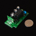
Breakout Board
- Front pins: GPIO12 GPIO13 GPIO14 GPIO4 GPIO5 GPIO15
- Back pins: GPIO16 GPIO0 GND TX RX VCC
- Pin arrangement for default firmware:
- GPIO13(D4) control the 1st relay
- GPIO12(D5) control the 2nd relay (pull up)
- GPIO14(D6) control the 3rd relay
- GPIO16(D7) control the 4th relay
- GPIO4 (D8) control the 5th relay
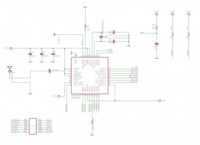
Schematic
Embedded Soldering
Firmware note
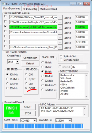
- Change SPI mode to DOUT, flash to 8MBit, should esp8266 normal at commands firmware or nodemcu, mostly same.
Reference Link
Documents
This category currently contains no pages or media.


