Category:Cortex Debug
Jtag
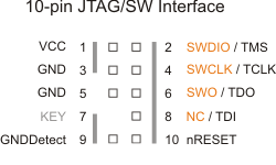
JTAG Signals Signal Connects to...
- TMS Test Mode State pin — Use 100K Ohm pull-up resistor to VCC.
- TDO Test Data Out pin.
- TDI Test Data In pin — Use 100K Ohm pull-up resistor to VCC.
- TCLK Test CLocK pin — Use 100K Ohm pull-down resistor to GND.
- VCC Positive Supply Voltage — Power supply for JTAG interface drivers.
- GND Digital ground.
- nRESET nRESET pin — Connect this pin to the (active low) reset input of the target CPU. Use 100K Ohm pull-up resistor to VCC. This is an open-collector/open-drain output.
Serial Wire
The Serial Wire mode is a different operating mode for the JTAG port, where only two pins are used for the communication. A third pin can be used optionally to trace data. JTAG pins and SW pins are shared.
- TCLK is SWCLK (Serial Wire Clock)
- TMS is SWDIO (Serial Wire debug Data Input/Output)
- TDO is SWO (Serial Wire trace Output)
Signal Connects to...
- SWDIO Data I/O pin. Use 100K Ohm pull-up resistor to VCC.
- SWO Optional trace output pin.
- SWCLK Clock pin. Use 100K Ohm pull-down resistor to GND.
- VCC Positive Supply Voltage — Power supply for JTAG interface drivers.
- GND Digital ground.
- nRESET nRESET pin — Connect this pin to the (active low) reset input of the target CPU. Use 100K Ohm pull-up resistor to VCC. This is an open-collector/open-drain output.
Reference
This category currently contains no pages or media.
