Capacitor Inductor Meter (Kit)
Build
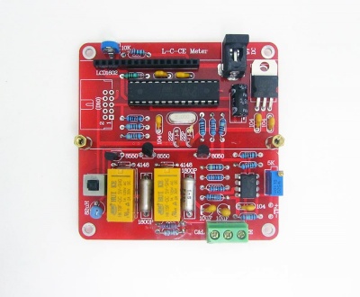
Attach all the parts from the lower to higher, attach all the resistors and inductors firstly, be careful of the value, then the capacitors and rest items.
Check all the values of resistors:
Check all the details below and make it wrong.
- The direction of electrolytic capacitor
- The direction of two titanium capacitors
- The direction of push buttons, marked as vertical line "|" should towards to bottom
And the final look
Debugging
After build, do not attach the IC and 1602 LCD first, connect your multimeter at the socket pin 7 and 22, voltage value should be 5V, then it is correct.
Calibration
- After Build, adjust the potentiometer on the top for the brightness of the LCD
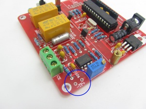
- Connect your own multimeter to the pin marked as "TP", and adjust potentiometer 5K near it until the multimeter show the voltage and 3.16V
- After these two steps, calibration is done.
And double check:
- Check IC socket pin 7 and 22 (VCC and GND), when 9V input is provided, the volt here should be 5V
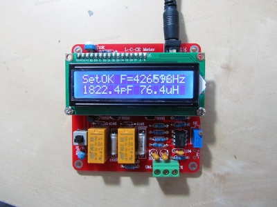
- setOK and should show, F=430684hz, 1842.2pf, 74-76uf, slightly difference will be fine.
Usage
Start and calibration
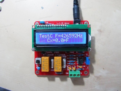
- This normally takes one minute, wait until you see the screen info below:
, normally value should be nearly 0 pf when NC connect - around 74-76uH inductor value is fine.
- Do not connect anything after you see this message on the LCD
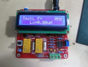
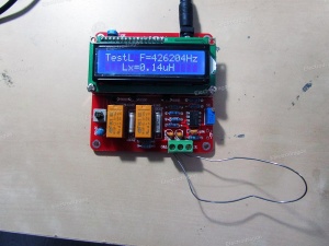
- Now press the button to switch to different measurement function
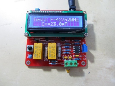
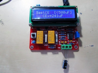
Testing Capacitor
Attach the capacitor on "C" and middle "COM"
