CSR8635
Features
| EX8635 | EX8645 |
|---|---|
| Bluetooth v4.0 A2DP v1.2; AVRCP v1.4; HFP v1.6; Single MIC input |
GAVDP1.2 HSP1.2; Dual MIC input |
- Model CSR8645/8635
- Bluetooth specification Bluetooth V4.0
- Modulation GFSK, π / 4 DQPSK, 8DPSK
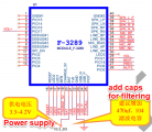
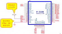
- Supply voltage DC3.3-4.2V, ≤3.0V automatic shutdown, ≤3.2V alarm
- Bluetooth protocol HFPV1.6, A2DPV1.2, AVRCPV1.4, HSPV1.2
- Working current ≤30mA for 8645, ≤13mA for 8635
- Standby current <50uA or 8645, <2mA for 8635
- Temperature range -40ºC ~ + 85ºC
- Wireless transmission range ≤10 meters
- Transmission power support Class1 / Class2 / Class3 maximum adjustable 9dbm for 8645, and 8dbm for 8635
- Sensitivity -80dBm <0.1% BER
- Frequency Range 2.4GHz ~ 2.480GHz
- External Interface USB (USB sound card)
- Audio performance supports ACC, MP3, SBC, APT-X decoder
- Audio SNR ≥75dB
- Distortion ≤0.1%
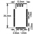
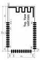
- Module size 26.2x13.5x0.8mm for 8645 and 24.5x14.1x2.0mm for 8635
- Adapter plate size 31x25mm for 8645 and 29x24mm for 8635
Dimension, Schematic
8645 board
8645 Convert board
8635 convert board
8635
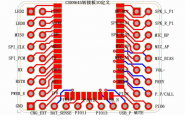
8635 pin definition
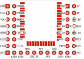
8645 pin definition
CSR8635 SCH 01
CSR8645 SCH 01


Pin Definition
- For 8645
Name Number IO IO IO Description
- 1 LED2 status indicator (not enabled)
- 2 LED1 status lights
- 3 LED0 status indicator
- 4 AIO0 not enabled
- 5 MISO burned into the program interface
- 6 CSB program burned into port
- 7 CLK burned into the program interface
- 8 MOSI burned into the program interface
- 9 SPI_EN burned into the program interface enable pin (high enable)
- 10 TX serial TX (not enabled)
- 11 RX serial RX (not enabled)
- 12 VBUS 5V input charging port
- 13 RST # low reset
- 14 BAT power input (3.3 ~ 4.2V)
- 15 POWER_EN module enable control, active-high (delay of 30ms must power)
- 16 1.8V 1.8V output
- 17 GND Power ground
- 18 CHG_EXT External Battery Charge Management
- 19 BAT_SENSE External Battery Charge Management
- 20 PIO10 not enabled
- 21 PIO11 not enabled
- 22 PIO12 not enabled
- 23 PIO13 not enabled
- 24 USB_N USB differential signal negative
- 25 USB_P USB differential signal positive
- 26 MUTE (PIO9) Mute control (mute, after a period of time is low)
- 27 PIO6 not enabled
- 28 PP / CALL (PIO7) Play / Pause / receive calls / back / re-pair
- 29 PIO8 not enabled
- 30 PREV (PIO18) on a
- 31 NEXT (PIO19) under a
- 32 VOL- (PIO20) Volume down
- 33 VOL + (PIO21) Volume up
- 34 MIC_BIAS Mike bias voltage
- 35 MIC_AN Mike 1 negative end
- 36 MIC_AP Mike 1 positive terminal
- 37 MIC_BN Mike 2 negative terminal (not enabled)
- 38 MIC_BP Mike 2 positive terminal (not enabled)
- 39 SPK_R_N1 audio right channel negative differential output terminal
- 40 SPK_R_P1 audio right channel positive differential output terminal
- 41 SPK_L_N1 Audio left channel differential output negative end
- 42 SPK_L_P1 audio left channel positive differential output terminal
- 43 RFOUT antenna (default built-in antenna, external disconnect)
- For 8635
Name Number IO IO IO Description
- 1 GND Power ground
- 2 PIO15 Unused
- 3 PIO14 Unused
- 4 PIO16 Unused
- 5 VOL + (PIO17) Volume up
- 6 PIO Debug debug port
- 7 PIO Debug debug port
- 8 PIO Debug debug port
- 9 PIO Debug debug port
- 10 SPI_PCM_EN unused
- 11 PCM1_IN / SPI_MOSI unused
- 12 PCM1_CLK / SPI_CLK unused
- 13 PCM1_OUT / SPI_MISO unused
- 14 PCM1_SYNC / SPI_CS unused
- 15 RESET low reset
- 16 LED2 Status Indicator
- 17 LED1 status lights
- 18 MFB / POWER module enable control, active-high (delay of 30ms must power)
- 19 CHARGE External Battery Charge Management (5V)
- 20 VBAT power input (3.3 ~ 4.2V)
- 21 1V8 1.8V output
- 22 GND Power ground
- 23 USB_N USB differential signal negative
- 24 USB_P USB differential signal positive
- 25 PP / CALL (PIO7) Play / Pause / receive calls / back / re-pair
- 26 MUTE (PIO0) Mute control (mute, after a period of time is low)
- 27 PREV (PIO6) on a
- 28 NEXT (PIO18) under a
- 29 VOL- (PIO21) volume reduction
- 30 LED3 is not enabled
- 31 LINE / MIC_AN Mike 1 negative end
- 32 LINE / MIC_AP Mike 1 positive terminal
- 33 MIC_BIAS Mike bias voltage
- 34 LINE_BN Mike 2 negative terminal (not used)
- 35 LINE_BP Mike 2 positive terminal (not used)
- 36 SPK_RN audio right channel negative differential output terminal
- 37 SPK_RP audio right channel positive differential output terminal
- 38 SPK_LN Audio left channel differential output negative end
- 39 SPK_LP audio left channel positive differential output terminal
- 40 GND Power ground
Design Circuits
| Type | schematic | note |
|---|---|---|
| Bluetooth power up on boot |
|
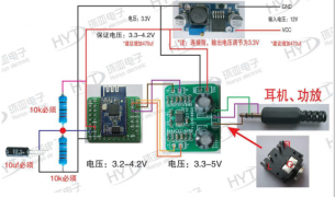
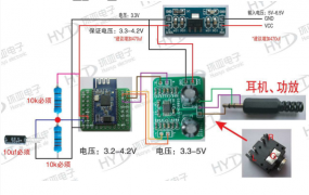
* VCC (3.3 ~ 4.2V), when using an external power supply: 3.3V (ASM1117) power supply. When using lithium batteries: lithium guarantee voltage between 3.3V ~ 4.2V;
|
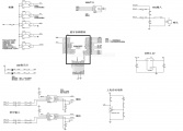
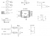
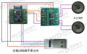
| Connect as USB card | * Simply access the module after Figure 4 and connected to the computer to be recognized as a USB sound card, driver-free;
| |
| Headset Connection | * Output to 3.5mm headphones or 3.5mm input soundbox
| |
| Differential four wires | * Auto enable on CTRL pin
| |
| Button Function | Example | |
| Status LED | * Before pairing, the two LEDs will blink in turns
| |
| Mic Input | Note the MIC has polarity | |
| Battery Charge | * Better to use a standalone charge module |


Design note
- If the next antenna modules have batteries, metal, LCD screen, speaker, and requires a minimum distance from the antenna 3cm, it is recommended to use an external antenna.
- Layout supply line is recommended when using the star alignment and ensure that the performance of the Bluetooth module power supply line is better. There BT, with op amp, amplifier, MCU, etc. separated, and the lower side of BT shall have no other interference, we recommend Bluetooth module on the bottom corner.
- It recommended that the module antenna portion of the float in the floor, but can not go around the antenna control cable, power cable, audio cable, MIC and other interference lines, if the module to be placed in the middle, to be slotted in around the antenna, it is recommended to use an external antenna .
- If there is row seat near the antenna module, housing a metal iron net impact on the signal, it is recommended to use an external antenna to solve the distance problem.
- When an external amplifier module to be connected to the differential input of the amplifier, if you do not take a differential input amplifier, you must be connected to a balance of the two differential amplifier level, otherwise there will be "pops" the impact of sound.
Reference Design Circuit
USB card
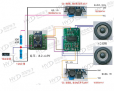
PAM8610 Amp Board
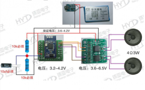
HT6872 Amp Board
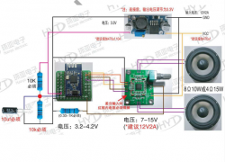
HT8696 Amp Board
Differential and headset
Differential and headset


QA
1. Can you give more details about the POWER_ENABLE/PW_E pin, for both module and breakout board, as they seem to be different ?
1. They are the same, breakout board pin directly connect to module.
2. Is this pin a logical input or output ? At what is its purpose ?
2. It is a boot pin to boot up the module, input.
3. When using the breakout board, the module boots up as soon as VBAT is connected, even with POWER_E not connected (float). How can I prevent unwanted boot up when battery is connected ? I want to use the internal charger while feeding +5V to VBUS with USB, so the battery needs to stay connected.
3. The breakout board, or called development module has auto boot circuit, please refer to its schematic. the part connect to MFB pin. Module don't have this.
4. Should I pull down this PWR_E pin in order to prevent the module to boot up, and to be able to control ON/OFF status of the module with an active high signal ?
4. For dev. board, remove R2 and Q1, when powered up, pull high to boot, and low to off
5. The breakout board have some additional components on the bottom side : hosting of 2 leds plus some other components. Do you have the schematics and explanations for these additional components ? What are M+ and M- pads ?
5. Yes in the wiki page, please check. M+ and M- is for microphone, purpose for speaking and calling.
7. On you wiki, for the switches/buttons, are installed with a 10k resistor and are connected to V3.3_SO, however the official documentation is using the 1V8 level without resistor. Is there any reason to use V3.3 + Resistor as active level instead of 1V8 ?
7. It is just for protection, not special reason.
8. I need to add some external low power components which needs a V3.3 voltage. Is there a way to get this power from the module ? The official documentation for CSR8645 gives information about a "3V3_USB" pin which gives direct access to the V3.3 internal rail.
9. The official documentation also mention a VREGENABLE pin in order to start and latch the power input regulation. Is there a way to use this feature ?
8+9 didn't use the IC regulator, don't have 3.3V output power. Please build extra circuits.