BLK IO
Control Commands

- Pin Definition
- All pins connect to ground pin of LED
- All commands should be end up with \r\n
| Pin | MCU PIN | v1.1 Command | v1.0 Command | Note | V1.1 Custom |
|---|---|---|---|---|---|
| 1 | PB5 | 1N - 1F | N1 - F1 | ||
| 2 | PB4 | 2N - 2F | N2 - F2 | ||
| 3 | PC3 | 3N - 3F | N3 - F3 | ||
| 4 | PC4 | 4N - 4F | N4 - F4 | ||
| 5 | PC5 | 5N - 5F | N5 - F5 | ||
| 6 | PC6 | 6N - 6F | N6 - F6 | ||
| 7 | PC7 | 7N - 7F | N7 - F7 | ||
| 8 | PD3 | 8N - 8F | N8 - F8 | Also BL status LED pin (1) | |
| 9 | PD2 | 9N - 9F | N9 - F9 | Set as input, connect to GND trigger send message | |
| 0 | PD4 | 0N - 0F | N0 - F0 | Set as input, connect to GND trigger send message | |
| A | PA1 | AN - AF | NA - FA | ||
| B | PA2 | BN - BF | NB - FB | ||
| C | PA3 | CN - CF | NC - FC |
- When Bluetooth made connection, BT status LED will keep constant high, you can not write it low, notice. But you can read the BT status via this pin.
Serial Debuging
- To receive MCU Debug Info, so USB-TTL <> MCU
- Use USB-TTL Debug tool, for example PL2303 TX (Green Color), RX (White Color)
- TX/G to right top pin, RX/W to right top second pin
- To receive phone bluetooth end message, vice verse connection.
Debug Note
- Do not connect serial cable when send commands remote from phone, will block message.
- Some module baudrate is 9600, 115200, 38400.
Code Update
- V1.12 get here File:BLKIOV1.1.hex.zip
- V1.12 fixed button delay bug
- V1.1 Custom Support PD2 PD4 as input, send message to bluetooth phone
Schematic
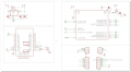
BLK IO SCH

On Board Bluetooth Module ED-30
- to change name -> AT+NAME<Param>
- to change pin -> AT+PIN<Param>
- to change baudrate -> AT+BAUD<Param>; <Param> from 1~C, 1: 1200, C: 1382400, 4: 9600, 8: 115200, 6: 38400