Instruction
Uploading arduino bootloader
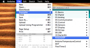
- Upload the ArduinoISP sketch into your arduino board
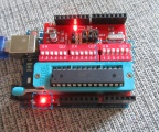
The setting of the LEDs from left to right are:
| LEDs |
Description |
Status
|
| D7 |
Programming |
when IC is programming properly
|
| D8 |
Error |
when target IC is not connecting properly
|
| D9 |
Status: heartbeat |
keep beating when power up
|
- Button Press for D10 to LOW TTL
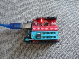
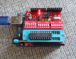
Setup the shield
Flash Bootloader Programming Guide and Note
- Support three attiny series
- Some version of ArduinoIDE is not working well, for example, 1.61, 1.00, etc, better version approved 1.05, 1.56-r2
- Burn bootloader twice, sometimes it seems the arduinoIDE bug: the IC will fail on uploading sketch when moved to arduino board
| Series |
DIP setup group |
Auto-rest |
ATtiny2313 jumper |
Core file supported 1.5 IDE |
LED
|
| ATtiny13/25/45/85/2313/4313 |
1st group |
up-off |
Down-off and On-up for attiny*313 |
LinkSource |
D3
|
| ATtiny24/44/84 |
2nd group |
up-off |
Down-off |
Link
|
| ATmega168/328 |
3rd group |
up-off |
Down-off |
default in IDE |
Digital pin 1 (D1)
|
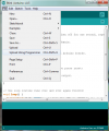
upload arduino sketch using "programmer" options in the menu, DO NOT use "upload" button
Program hex file into target IC with AVRDUDESS
Board setup
- Set the auto-reset to off, now you will only program the target IC
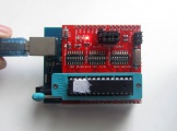
- Set the right jumpers for ICs, see the examples below, ONLY turn on one group of toggle switch every time.
For attiny13a, Turn on the 1st group on the left
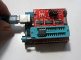
For attiny 2313, turn on the 1st group in the left and put the four jumpers on the right top position
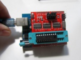
For atmega 328p, turn on the 3rd group on the right
For new board version attiny13
For new board version attiny2313
For new board version atmega328
Programming from PC
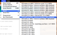
Select the correct board and serial port
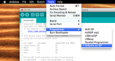
Select arduino as ISP in programmer menu (Your Arduino on the bottom should be already programmed within Arduino as ISP sketch, and heartheat LED is beating)
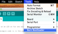
Click burn bootloader, do it twice for a bug reason (some arduinoIDE versions have problem)
Upload blink sketch for testing
- To check the bootloader, you can try upload sketch
- To upload sketch to the IC on the shield, choose "upload using programmer" in the menu, otherwise it will upload into arduino main board
- or using avrdudess to upload AVR hex file
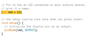
- Do not program the LED pin 13, then LED on the shield will not work, use following settings instead
| Series |
Blink sketch for testing LED on shield
|
| ATtiny13/25/45/85/2313/4313 |
int led = 4; (attiny13, etc), int led = 1;(attiny2313, etc)
|
| ATtiny24/44/84 |
?
|
| ATmega168/328 |
int led = 1;
|
Video tutorials
