Difference between revisions of "HLW8032 SDK"
(No difference)
|
Latest revision as of 14:44, 30 December 2021
HLW8032
- Make sure use baud rate 4800 to read data
- Demo Video HLW8012 http://v.youku.com/v_show/id_XMjY3ODQ5ODMxMg==.html
- Demo code here, initiate version - https://github.com/Edragon/Arduino/tree/master/Sketchbook/04_sensor
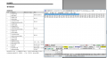
register reading of by PL2303TA, 4800bps, each group of data is 24 bytes, please note this is reading non-load

Tips to use with ESP8266:
Method 1
- Use Wemos and its softserial, wiring should be
- HLW8032 RX to Wemos D5
- HLW8032 3.3V to Wemos 5V or 3.3V
- HLW8032 GND pin to Wemos GND
- Upload sketch this one to wemos, Open serial monitor to check data, notice raw data in HEX ouptut
- Bypass on board AC-DC converter to analyze data directly, see post here.
Method 2 (obsolete)
- The wiring should be:
HLW8032 RX -> ESP8266 RX pin
HLW8032 3.3V -> ESP8266 3.3V, also works on 5V
HLW8032 GND -> ESP8266 GND
- Better not use with wemos board, which has USB-TTL UART bridge circuits on board, could cause conflict to uart reading from hlw8032. Please use a standalone ESP8266 module or board, without this circuits, for example our esp-12f adapter board
- Better not use with ESP-link firmware, data can be read, but not in the raw hex data. Better write your own code to read and analyze the data by esp8266
- Again double check baudrate should be 4800, in case for ESP-LINK, options should set to "8E1", data could be read but incomplete
- The test could see here: https://twitter.com/electro_phoenix/status/1104004115422539781
- Not yet have demo code of this available now.
Analyze Data
- total 24 bytes per transfer
| Note | state | check | V_para REG | V_val REG | I_para REG | I_val REG | P_para REG | P_val REG | Data Update REG | PF REG | CheckSum REG |
|---|---|---|---|---|---|---|---|---|---|---|---|
| Data read from HLW8032-ISO, NO LOAD | FA | 5A | 02 EE C8 | FE FF 01 | 00 3F 66 | 00 00 00 | 51 21 88 | FA DB 29 | 01 | 00 00 | 54 |
FA 5A  02 EE C8  FE FF 01  00 3F 66  00 00 00  51 21 88  FA DB 29  01 00 00 54
FA 5A  02 EE C8  FE FF 01  00 3F 66  00 00 00  51 21 88  FC 75 8D  01 00 00 54
FA 5A  02 EE C8  FE FF 01  00 3F 66  00 00 00  51 21 88  FE 0E F2  01 00 00 54
FA 5A  02 EE C8  FE FF 01  00 3F 66  00 00 00  51 21 88  FE FF 01  01 00 00 54
- Switching Hex to DEC, for example for V_para 02 EE C8 = HEX2DEC ( 02 ) * 65536 + HEX2DEC ( G24 ) * 256 + HEX2DEC ( H24 )
- Voltage = (V_para / V_val) * Vk
Vk = 1.88 ( by 4*470K resistors ladder)
- Current = (I_para / I_cal) * Ik
Ik = 1 (1mR current sensing resistor)
- Power = ( P_para / P_val ) * Vk * Ik
- Data read when only power by 5V, not load, not yet connect to AC mains
55 5A  02 DA 78  07 26 72  00 3D 3B  07 27 5B  4C C4 58  D0 A7 87  61 00 01 BC
F2 5A  02 DA 78  07 28 BB  00 3D 3B  04 35 B5  4C C4 58  11 9F 4F  61 00 00 6C =>
F2 / 5A / 02 DA 78 / 07 28 BB / 00 3D 3B / 04 35 B5 / 4C C4 58 / 11 9F 4F / 61 / 00 00 / 6C =>
state: F2 / check: 5A / Voltage parameter REG: 02 DA 78 / Voltage REG: 07 28 BB / Current Parameter REG: 00 3D 3B / Current REG: 04 35 B5 / Power parameter REG: 4C C4 58 / Power REG: 11 9F 4F / Data Updata REG: 61 / PF REG: 00 00 / CheckSum REG: 6C
ISO Version
ZMPT Sensors (on isolated version)

Current-type Voltage Sensor ZMPT107
- Input AC voltage side: Sensor Nominate curernt 2mA = 220 / 100K (sample resistor) about 2.195mA
- 2mA is the typical working current of sensor, both side are equal current 2.195mA
- Output ACvoltage side: Output voltage for read = 2.195mA * 51R (sample resistor) = 0.112Vac
Current Sensor ZMCT103C
- output current up to 5mA
- 5mA * 1R = 0.005Vac
Any questions please read more details in datasheet
voltage transformer
Current type voltage transformer
Specifications: 1000: 1000, 2mA / 2mA
Voltage coefficient = 150k / (49.9 * 1000) = 3.006
Current Transformer
Specifications: 1: 1000, 5A / 5mA
Current coefficient = 1000/1000 * 1 = 1
Use Isolated ZMPT Sensor Version
- Find the design documents (chinese) here
- Use a already-known load to calculate the coefficience first
- The math for Voltage is, same for current and power, voltage value is in register bit 2~4, voltage_value is 5~7
Voltage = (voltage_register / voltage_value) * voltage_coefficent.
- For example for voltage 220V, you can calculate the value of voltage_coefficent
22V = (voltage_register / voltage_value) * voltage_coefficent.
* Use voltage_coefficent as a constant value for further reading.
- Notice voltage_register is different for every chip.
Use with ESP8266
- Data should be sent to hardware serial of ESP8266, softwareserial seems not working correctly (lose)
- Please refer to the ESP8266 library in documentation section
Calibration
- But because the error of each module is different, the scale factor is different.
- Therefore, each module needs to be calibrated separately, so we need to calibrate the module for a known load (known power, voltage and current parameters),
- And save the corresponding register data in EEPROM, this group of data can be applied to the calculation of another group of unknown load parameters (power, voltage and current).
Documentation
Arduino Mega
ESP8266