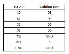
|
|
| Line 8: |
Line 8: |
| [[File:TSC table.jpg]] | | [[File:TSC table.jpg]] |
|
| |
|
| ==Example code==
| |
| * Get the necessary timerone library here [[:File:TimerOne.zip|TimerOne.zip]]
| |
| <syntaxhighlight lang="Arduino">
| |
| #include <TimerOne.h>
| |
|
| |
| #define S0 6 // Please notice the Pin's define
| |
| #define S1 5
| |
| #define S2 4
| |
| #define S3 3
| |
| #define OUT 2
| |
|
| |
| int g_count = 0; // count the frequecy
| |
| int g_array[3]; // store the RGB value
| |
| int g_flag = 0; // filter of RGB queue
| |
| float g_SF[3]; // save the RGB Scale factor
| |
|
| |
|
| |
| // Init TSC230 and setting Frequency.
| |
| void TSC_Init()
| |
| {
| |
| pinMode(S0, OUTPUT);
| |
| pinMode(S1, OUTPUT);
| |
| pinMode(S2, OUTPUT);
| |
| pinMode(S3, OUTPUT);
| |
| pinMode(OUT, INPUT);
| |
|
| |
| digitalWrite(S0, LOW); // OUTPUT FREQUENCY SCALING 2%
| |
| digitalWrite(S1, HIGH);
| |
| }
| |
|
| |
| // Select the filter color
| |
| void TSC_FilterColor(int Level01, int Level02)
| |
| {
| |
| if(Level01 != 0)
| |
| Level01 = HIGH;
| |
|
| |
| if(Level02 != 0)
| |
| Level02 = HIGH;
| |
|
| |
| digitalWrite(S2, Level01);
| |
| digitalWrite(S3, Level02);
| |
| }
| |
|
| |
| void TSC_Count()
| |
| {
| |
| g_count ++ ;
| |
| }
| |
|
| |
| void TSC_Callback()
| |
| {
| |
| switch(g_flag)
| |
| {
| |
| case 0:
| |
| Serial.println("->WB Start");
| |
| TSC_WB(LOW, LOW); //Filter without Red
| |
| break;
| |
| case 1:
| |
| Serial.print("->Frequency R=");
| |
| Serial.println(g_count);
| |
| g_array[0] = g_count;
| |
| TSC_WB(HIGH, HIGH); //Filter without Green
| |
| break;
| |
| case 2:
| |
| Serial.print("->Frequency G=");
| |
| Serial.println(g_count);
| |
| g_array[1] = g_count;
| |
| TSC_WB(LOW, HIGH); //Filter without Blue
| |
| break;
| |
|
| |
| case 3:
| |
| Serial.print("->Frequency B=");
| |
| Serial.println(g_count);
| |
| Serial.println("->WB End");
| |
| g_array[2] = g_count;
| |
| TSC_WB(HIGH, LOW); //Clear(no filter)
| |
| break;
| |
| default:
| |
| g_count = 0;
| |
| break;
| |
| }
| |
| }
| |
|
| |
| void TSC_WB(int Level0, int Level1) //White Balance
| |
| {
| |
| g_count = 0;
| |
| g_flag ++;
| |
| TSC_FilterColor(Level0, Level1);
| |
| Timer1.setPeriod(1000000); // set 1s period
| |
| }
| |
|
| |
| void setup()
| |
| {
| |
| TSC_Init();
| |
| Serial.begin(9600);
| |
| Timer1.initialize(); // defaulte is 1s
| |
| Timer1.attachInterrupt(TSC_Callback);
| |
| attachInterrupt(0, TSC_Count, RISING);
| |
|
| |
| delay(4000);
| |
|
| |
| for(int i=0; i<3; i++)
| |
| Serial.println(g_array[i]);
| |
|
| |
| g_SF[0] = 255.0/ g_array[0]; //R Scale factor
| |
| g_SF[1] = 255.0/ g_array[1] ; //G Scale factor
| |
| g_SF[2] = 255.0/ g_array[2] ; //B Scale factor
| |
|
| |
| Serial.println(g_SF[0]);
| |
| Serial.println(g_SF[1]);
| |
| Serial.println(g_SF[2]);
| |
|
| |
| }
| |
|
| |
| void loop()
| |
| {
| |
| g_flag = 0;
| |
| for(int i=0; i<3; i++)
| |
| Serial.println(int(g_array[i] * g_SF[i]));
| |
| delay(4000);
| |
|
| |
| }
| |
|
| |
|
| </syntaxhighlight>
| |
| [[File:TSC COM.jpg]] | | [[File:TSC COM.jpg]] |
|
| |
|
| |
| [[category:Sound, light, etc]]
| |
