Category:JDY-25M
Revision as of 17:31, 21 May 2021 by Chao (talk | contribs) (Created page with "== Pin Definitions == thumb|right * 1 VCC power supply (1.8-3.6V) * 2 NC empty spindle * 3 NC empty spindle * 4 NC empty spindle * 5 INPUT...")
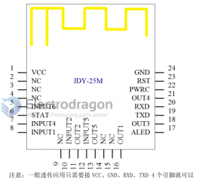
Pin Definitions
- 1 VCC power supply (1.8-3.6V)
- 2 NC empty spindle
- 3 NC empty spindle
- 4 NC empty spindle
- 5 INPUT 5 Input 5 In MESH mode, the button supports the IO initialization of the specified device
- 6 STAT STAT is not connected in series in non-MESH mode, and under high saturation MESH mode after connection (successfully connected to the network, output high expectations, not scheduled)
- 7 INPUT3 Input 3 In MESH mode, the button supports IO initialization to control the specified device
- 8 INPUT1 Input 1 In MESH mode, the button supports to control the IO access of the specified device
- 9 NC
- 10 INPUT2 Input 2 In MESH mode, the button supports the IO initialization of the specified device
- 11 OUT2 output 2 default value, in the networking state, support serial command control and input KEY spindle control
- 12 INPUT4 Input 4 In MESH mode, the button supports to control the IO access of the specified device
- 13 OUT5 outputs 5 default variables, in the networking state, supports serial port command control and input KEY spindle control
- 14 NC empty spindle
- 15 NC air shaft
- 16 OUT1 output 1 default value, in the networking state, support serial command control and input KEY spindle control
- 17 ALED broadcast LED indication in very MESH mode (flashing when not connected, always on after connecting)
- 18 OUT3 output 3 default value, in the networking state, support serial port command control and input KEY spindle control
- 19 TXD serial output serial output, allowing TTL priority
- 20 RXD serial port input serial port input, allowing TTL range
- 21 OUT4 output 4 is the default starting point. In the networking state, it supports serial port command control and input KEY spindle control
- 22 PWRC sleep wake-up reset In the deep sleep state, support PWRC sleep wake-up, pull down the connection state to support AT command
- 23 RST reset Temporary reset, high availability work (floating for high replacement)
- 24 GND Ground Power Ground
Default factory settings
- 1 Baud rate 9600 AT+BAUD4
- 2 Module short address = 2 bytes of later MAC address
- 3 Network ID number 1189 AT+NETID1189
- 4 K1 target short address FFFF AT+KEY1,FFFF,1,1
- 5 K2 target short address FFFF AT+KEY2,FFFF,2,1
- 6 K3 target short address FFFF AT+KEY3,FFFF,3,1
- 7 K4 target short address FFFF AT+KEY4,FFFF,4,1
- 8 K5 target short address FFFF AT+KEY5,FFFF,5,1
- 9 APP connection password switch OFF AT+TYPE0
- 10 APP connection password 123456 AT+PIN123456
- 11 Broadcast name JDY-25M AT+NAME JDY-25M
- 12 Router node 0 AT+MCLSS0
- 13 Transmit power 4 AT+POWR4
- 14 OUTPUT and INPUT are not related 0 AT+SUBTYPE0
- 15 Learning mode off 0 AT+LEARN0
