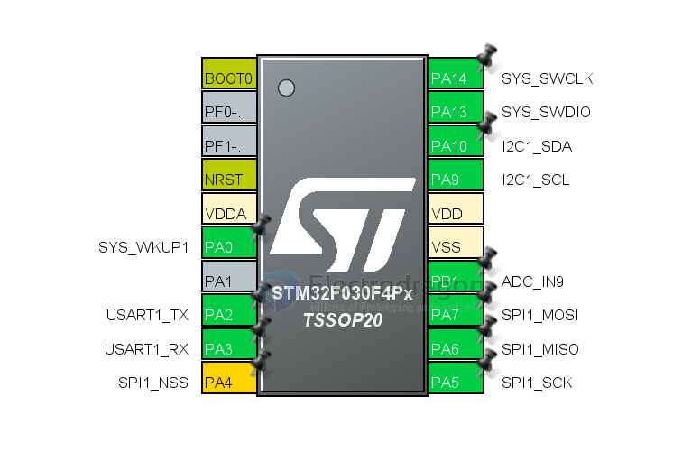
STM32F0 HDK
BSP
- LED PA4
- Default UART
PA9 - TX
PA10 - RX
- Remap
 Serial1.setRx(PA3);
 Serial1.setTx(PA2);
 Serial1.begin(9600);
- Better use for I2C, for arduino STM32Duino
 Wire.setSDA(PA10);
 Wire.setSCL(PA9);
 Wire.begin();
- BUTTON NRST
STM32F030F4P6 Features
Core: ARM® 32-bit Cortex® -M0 CPU, frequency up to 48 MHz
Memories
- 16 to 256 Kbytes of Flash memory
- 4 to 32 Kbytes of SRAM with HW parity
- CRC calculation unit
- Reset and power management
- Digital & I/Os supply: VDD = 2.4 V to 3.6 V
- Analog supply: VDDA = VDD to 3.6 V
- Power-on/Power down reset (POR/PDR)
- Low power modes: Sleep, Stop, Standby
Clock management
- 4 to 32 MHz crystal oscillator
- 32 kHz oscillator for RTC with calibration
- Internal 8 MHz RC with x6 PLL option
- Internal 40 kHz RC oscillator
- Up to 55 fast I/Os
All mappable on external interrupt vectors
Up to 55 I/Os with 5V tolerant capability
5-channel DMA controller
One 12-bit, 1.0 μs ADC (up to 16 channels)
- Conversion range: 0 to 3.6 V
- Separate analog supply: 2.4 V to 3.6 V
- Calendar RTC with alarm and periodic wakeup from Stop/Standby
- 11 timers
- One 16-bit advanced-control timer for six-channel PWM output
- Up to seven 16-bit timers, with up to four IC/OC, OCN, usable for IR control decoding
- Independent and system watchdog timers
- SysTick timer
Communication interfaces
- Up to two I2 C interfaces
- Up to six USARTs supporting master synchronous SPI and modem control; one with auto baud rate detection
- Up to two SPIs (18 Mbit/s) with 4 to 16 programmable bit frames
- Serial wire debug (SWD)

