Category:BC-04
Basic
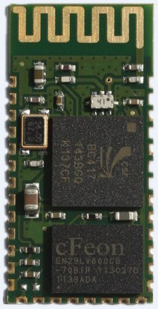
Based on British CSR BlueCore4-Ext chip, follow V2.1 + EDR Bluetooth specification. The module supports UART, USB, SPI, PCM, SPDIF interface, and support for the SPP Bluetooth serial protocol, low cost, small size, low power consumption, send and receive sensitivity advantages, just with a few external components will be able to achieve its powerful. Feature:
- Bluetooth V2.1 + EDR
- Bluetooth Class 2
- Built-in PCB RF antenna
- Built-in 8Mbit Flash
- Support for SPI programming interface
- Support UART, USB, SPI, PCM interface
- 3.3V power supply
- REACH, ROHS certification
Application: The module is mainly used for short-range wireless data transmission field. Convenient and connected to the PC, Bluetooth devices can also data exchange between the two modules. Avoid cumbersome cable connections, direct replacement for the serial line.
- Bluetooth wireless data transmission;
- industrial remote control, telemetry;
- POS system, wireless keyboard, mouse;
- traffic, underground positioning, alarm;
- automated data acquisition system;
- wireless data transmission; banking system;
- wireless data acquisition;
- building automation, security, wireless monitoring room equipment, access control systems;
- smart home, industrial control;
- automotive testing equipment;
- television the interactive program vote Equipment;
- government street light energy saving equipment
- wireless LED display system
- Bluetooth joystick, Bluetooth gamepad
- Bluetooth printer
- Bluetooth remote control toy
Mechanical Features:
- Operating Frequency Band 2.4GHz -2.48GHz unlicensed ISM band
- Bluetooth Specification V2.1+EDR
- Output Power Class Class 2
- Operating Voltage 3.3V
- Host Interface USB 1.1/2.0 or UART
- Audio Interface PCM interface
- Flash Memory Size 8Mbit
- Dimension 27mm (L) x 13 (W) mm x 2mm (H)
Electric Features:
- Absolute Maximum Ratings
- Rating Min Max
- Storage temperature -40℃ +150℃
- Supply voltage: VBAT -0.4V 5.6V
- Other terminal voltages VSS-0.4V VDD+0.4V
- Recommended Operating Conditions
- Operating Condition Min Max
- Operating temperature range -40℃ +150℃
- Guaranteed RF performance range(a) -40℃ +150℃
- Supply voltage: VBAT 2.2V 4.2V(b)
Power Consumption:
- Operation Mode Connection Type UART Rate(kbps) Average Unit
- Page scan - 115.2 0.42 mA
- ACL No traffic Master 115.2 4.60 mA
- ACL With file transfer Master 115.2 10.3 mA
- ACL 1.28s sniff Master 38.4 0.37 mA
- ACL 1.28s sniff Slave 38.4 0.42 mA
- SCO HV3 30ms sniff Master 38.4 19.8 mA
- SCO HV3 30ms sniff Slave 38.4 19.0 mA
- Standby Host connection - 38.4 40 µA
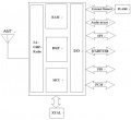
Function Diagram, Dimension
Schematic and reference design
LED Status
| Mode | LED Status | Module Status |
|---|---|---|
| Master | Even blinking, 150ms on/off | searching mode |
| Master | 5 times fast blinking, 2 seconds off | pairing with recorded paired device |
| Master | Keep on | Connected |
| Slave | Even blinking 800ms on, 800ms off | wait for pairing |
| Slave | Long-time on | Connected |
- Slave mode LEDs
- Status indicating LED: PIO(1), Use to indicating the status of the Bluetooth module, LED light flashes with the Bluetooth module state corresponding to the following table:
| Mode | Header text | Header text |
|---|---|---|
| Slave | Even Speed rapid flashing (200ms on/off) | waiting for matching |
| Slave | always on | waiting for connection |
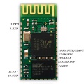
Pin Definition
| Pin Number | Name | Type | Decription | Programmed for BC04-B |
|---|---|---|---|---|
| 1 | UART-TX | CMOS output | UART data output | Same |
| 2 | UART-RX | CMOS input | UART data input | Same |
| 3 | UART-CTS | CMOS input | UART cancel send | - |
| 4 | UART-RTS | CMOS output | UART request send | - |
| 5 | PCM-CLK | Double way | PCM clock | - |
| 6 | PCM-OUT | CMOS output | PCM data output | - |
| 7 | PCM-IN | CMOS input | PCM data input | - |
| 8 | PCM-SYNC | double way | Sync PCM data | - |
| 9 | AIO(0) | double way | Programmable Analog I/O | - |
| 10 | AIO(1) | double way | Programmable Analog I/O | - |
| 11 | RESETB | CMOS input | Low TTL to reset | - |
| 12 | 3.3V | Power Input | Power 3.3V | Same |
| 13 | GND | Power Output | GND | Same |
| 14 | NC | output | Please NC it | - |
| 15 | USB-DN | double way | USB data negative | - |
| 16 | SPI-CSB | CMOS input | SPI chip selection | - |
| 17 | SPI-MOSI | CMOS input | SPI data input | - |
| 18 | SPI-MISO | CMOS output | SPI data output | - |
| 19 | SPI-CLK | CMOS input | SPI clock | - |
| 20 | USB-DP | double way | USB data positive | - |
| 21 | GND | GND | GND | - |
| 22 | GND | GND | GND | - |
| 23 | PIO(0) | double way | Programmerable I/O (0) | - |
| 24 | LED | output | Status indicating LED | Status indicating LED
|
| 25 | MCU-INT | double way | Programmerable I/O (2) | MCU interrupts port |
| 26 | Clear | double way | Programmerable I/O (3) | Memory clear key (short press) Restore Defaults button (long press 3s) |
| 27 | SW/HW | double way | Programmerable I/O (4) | Software / hardware main from settings port
|
| 28 | Master/Slave | double way | Programmerable I/O (5) | Hardware master-slave mode settings port
|
| 29 | PIO(6) | double way | Programmerable I/O (6) | - |
| 30 | PIO(7) | double way | Programmerable I/O (7) | - |
| 31 | PIO(8) | double way | Programmerable I/O (8) | - |
| 32 | PIO(9) | double way | Programmerable I/O (9) | - |
| 33 | PIO(10) | double way | Programmerable I/O (10) | - |
| 34 | PIO(11) | double way | Programmerable I/O (11) | - |
Layout design points
- BC04 Bluetooth module TTL level required to 3.3V, and for 5V TTL you will need 3.3-5V TTL conversion circuit.
- Bluetooth signal by around a great impact, such as trees, metal, walls and other obstacles will Bluetooth signal absorption or shielding, so is not recommended being installed in a metal enclosure.
- the metal will weaken the antenna, it is recommended that you should not paving and traces below the antenna in the layout design, preferably hollowed.
BC04 Breakout Board
Reference schematic
Documents
- The demo video of the current draw of BC04B module here.
- Check here Phone and Arduino Bluetooth Communication to see how it works with arduino and cell phone.
- Use UART PC software to write AT commands.


