EDRF3
RF Link with Decoder/Receiver
Pin definitions ANT、GND、LED、SW、VT、D0、D1、D2、D3、VDD、GND
- ANT - antenna,
- LED - external singal status LED
- SW - external learning switch
- VT - same as LED
- D0-D3 - Data output
- VDD - Power posistive in
- GND - Power ground
working mode
- T2 T1 off - default point mode
- T2 connect T1 off - lock mode
- T2 off T1 connect - inter-lock mode
How to pair
- Learning and pairing:
- Hold learning button for 2 seconds and release,
- LED blink once, enter into pair mode
- on transmisster, press any button to pair
- receiver board receive signal, LED blink 4 times means succeed.
- Clean pair
- pair button hold more than 8 seconds, LED up, after 8 seconds LED off means succeed clean.
RF Link with Encoder and Decoder PT2262/PT2272
Pin Definition, Modes, Antenna, Encrption
| Pins (From left to right on top side) | Function |
|---|---|
| VT | Receive signal (optional) |
| D3 | Data output |
| D2 | Data output |
| D1 | Data output |
| D0 | Data output |
| 5V | 5V Power Supply |
| GND | GND |
- Data output of receiver will be the same of data send from remote controller, so in theory, when you push button 1, you will get 0001 from D0~03, and when you push button 2, you will get 0010 accordingly.
About Modes setup
- M4(push-down: hold for output, unhold to stop output)- this is default mode
- L4(interlock:only one of four of the output can work in the same time)
- T4(selflock: four output are independent, push once to output and push again to stop)
About Extra Antenna on Receiver - If your require more far tranmission distance, it is better to use 1/4 wavelength antenna, 50 ohm single-core wire, the length of the antenna is about 23cm for 315M, and 17CM for 433M. Solder it on ANT pad.
About - Further Encryption

- This RF link works as fixed code encryption, not the high level security, but will good enough for many normal cases, like car garage door.
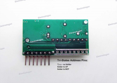
- A0~A7 pins are the address pins, on both transmitter and receiver should be matched for communication.
- These pins has three states: float, to VCC, to GND.