ESP8266 Adapter Board
Esp8266 Module Adapter Board
Note
- The adapter is a little small, must solder the wifi board onto it carefully.
- Reset the board after flash
- From version 2.1, the serial interface is 5V compatible, can use 5V USB-TTL program directly. Old version can work, but can not reach highest speed.
- Only need power 3V3 GND for power up the module, and TX, RX for serial communication.
Pin Definition, Dimension
| Left Side Pins | Note | Right Side Pins | Note |
|---|---|---|---|
| RST | Pull-up & Reset-Button | TXD | |
| ADC | - | RXD | |
| EN | Pull-up | 4 | |
| IO16 | - | 5 | |
| IO14 | - | 0 | Pull-up & Flash-Button |
| IO12 | - | 2 | Pull-up |
| IO13 | - | 15 | Pull-down |
| 3V3 | - | GND | |
| CS | - | CLK | |
| DI | - | DO | |
| IO09 | - | IO10 | |
| VIN | - | GND |
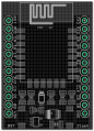
Pin definition and size, ESP adapter board R2
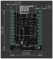
Pin definition and size, ESP adapter board R3


- old pin definition please see this one File:ESP 12E Board Electrodragon.pdf