(diff) ← Older revision | Latest revision (diff) | Newer revision → (diff)
Usage
See at-commands for how to make phone call and send message.
Schematic
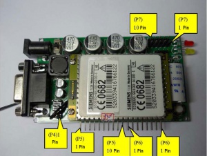
Pin Definition
| Group |
Pin Number |
Description |
Remark
|
| P4 |
1 |
RXD_PC_TTL |
PC/MCU/TC35 TTL Connector
|
| P4 |
2 |
TXD_PC_TTL |
|
| P4 |
3 |
RXD_MCU_TTL
|
| P4 |
4 |
RXD_35_TTL
|
| P4 |
5 |
TXD_35_TTL
|
| P4 |
6 |
TXD_MCU_TTL
|
| P4 |
7 |
RXD_PC_TTL
|
| P4 |
8 |
TXD_PC_TTL
|
| Group |
Pin Number |
Description |
Remark
|
| P5 |
1 |
VCC12V |
External Battery
|
| P5 |
2 |
GND |
GND
|
| P5 |
3 |
VCC |
Module Power Supply
|
| P5 |
4 |
GND |
GND
|
| P5 |
5 |
RXD_PC_232 |
PC 232 Receive/Send Connector
|
| P5 |
6 |
TXD_PC_232 |
PC 232 Receive/Send Connector
|
| P5 |
7 |
RXD_35_TTL |
TC35 232 Receive/Send Connector
|
| P5 |
8 |
TXD_35_TTL |
TC35 232 Receive/Send Connector
|
| P5 |
9 |
TXD_MCU_TTL |
External MCU 232 Receive/Send Connector
|
| P5 |
10 |
RXD_MCU_TTL |
External MCU 232 Receive/Send Connector
|
| Group |
Pin Number |
Description |
Remark
|
| P6 |
1 |
VCC |
Module Power Supply
|
| P6 |
2 |
PD |
Close Module
|
| P6 |
3 |
RING |
Incoming Call Indicator
|
| P6 |
4 |
SYNC |
Signal Indicator
|
| P6 |
5 |
LOW_BAT |
Back up battery
|
| P6 |
6 |
VDD |
|
| P6 |
7 |
AKKU_TEMP |
Battery temperature check
|
| P6 |
8 |
POWER |
|
| Group |
Pin Number |
Description |
Remark
|
| P7 |
1 |
EPP1 |
Ear phone 1 Positive
|
| P7 |
2 |
EPN1 |
Ear phone 1 Negative
|
| P7 |
3 |
GND |
GND
|
| P7 |
4 |
MICP1 |
Microphone 1 Positive
|
| P7 |
5 |
MICN1 |
Microphone 1 Negative
|
| P7 |
6 |
EPP2 |
Ear phone 2 Positive
|
| P7 |
7 |
EPN2 |
Ear phone 2 Negative
|
| P7 |
8 |
GND |
GND
|
| P7 |
9 |
MICP2 |
Microphone 2 Positive
|
| P7 |
10 |
MICN2 |
Microphone 2 Negative
|
Reference
External circuit Design

