SIMCOM Old
Obsolete (outdated should NOT use)
SIM800-Mini
Board interface
- D100 LED indicator
- CN101 6pin 2.54mm header interface
- J100 GPRS/GSM ANT
- J102 BT ANT(only for SIM800H)
- CN100 Micro SIM card socket
- C102 VRTC(Not mounted by default)
- TEST 2.8V
Common Pin Definition
- Power supply should provide sufficient current so that the module can work normally; the peak current is nearly 2A, will NOT work over 4.4V
| name | pin | mark on pcb | Description | Comment |
|---|---|---|---|---|
| GND | 1 and 6 | G | ground | |
| Vbat | 2 | V | Power range is from 3.4V to 4.4V. | Zenger diode is strongly recommended to anti surge on VBAT |
| PWRkey | 3 | K | Power down | Shorted with GND via R104 by default |
| TXD | 4 | T | Transmit Data | TTL Series data Output |
| RXD | 5 | R | Receives Data | TTL Series data Input |
SIM800C-Full Board R1-old
- Pin Definition
| Pin | Description | Pin | Description |
|---|---|---|---|
| GND | Power ground | VCC_IN | power supply pin, input DC5V-20V, used to power the board |
| RI | The kernel ringing pin | DTR | Data terminal preparation |
| TXD | module serial send pin, TTL level (not directly connected to the RS232 level) | RXD | module serial receive pin, TTL level (not directly connected to the RS232 level) |
| U2_R | module serial port 2 receive pin | U2_T | Module serial port 2 transmit pin |
| V_M | This pin is used to convert the TXD and RXD of the GSM module board to the TTL logic of the corresponding target board. This is used to convert the TXD and RXD of the GSM module board to the corresponding TTL logic | ADC | ADC detection |
| SPP | Core audio output pin | SPN | Core audio output pin |
| MC- | Core audio input pin | MC + | Core audio input pin |
| PWR | Pull down this pin to enable the module to be turned on or off | BAT | lithium battery input pin, 3.3v-4.4v |
Note
- VBAT MUST be lower than 4.4V, 4.0V is recommended, and TXD/RXD are TTL level which can be directly connected with MCU.
- Test pin, sim card voltage: Should confirm whether SIM card is inserted, and voltage test points should be 2.8V.
- Bluetooth must have enough current, USB power can not supply enough current
SIM900
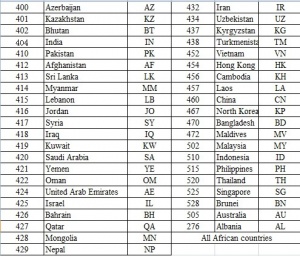
Supported countries for sim900A - > click to see on right side
Schematic
Pin functions of SIM908
- Pin RI: can indicate the incoming call with a TTL signal, this can also connect to a MCU port, it is connected to Net1 onboard LED too.
- Board provide VCHG battery charge pin: as well as a temperature check pin for battery, when a lithium battery attach between pin VCHG and GND, it will be charged by a provided 4.2 volt.
SIM908 Dev. Board
Configuration
| Name | Description |
|---|---|
| SW101 | Power On/Off |
| GSM PORT | Serial (AT command input,GPRS data input) |
| GPS PORT | GPS debug test |
| LED D200 | Power indication LED |
| LED D201 | Working status indication LED |
| CN102 | USB Port |
| J103 | GSM Antenna Port |
| J100 | GPS Antenna Port |
Reference voltage test point
| Reference voltage test point | Voltage |
|---|---|
| Test Point 1 | 3.3V |
| Test Point 2 | 5.0V |
| Test Point 3 | 4.0V |
| Test Point 4 | 2.8V |
SIM908 Mini Board
Status of On-board LEDs
| Name | Description |
|---|---|
| Net1 | connect to pin RI, keep off when power on, will light on when there is an incoming call |
| Pwr | Power status LED, keep constantly on |
| Net | inform the network status, quick blink when network not yet registered or problematic, keep slowly blink when network registered. |
Updates
- Version 1.1: * Change main power LDO, may have better performance * Add extra power pins and Uart pins * Fit into a case design.
- Version 1.2: Add extra logic leveled UART pins for arduino or Raspbery Pi such 5V or 3v3 devices
