NRF905
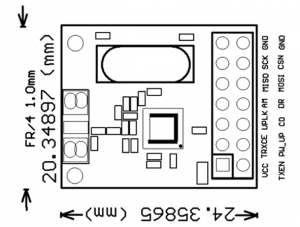
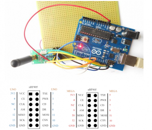
Pin Definition and Size
- VCC ---- Power supply.
- TXE ---- RF module mode selecting.
- CE ---- Enable RF module for transmit and receive.
- PWR ---- Power up chip.
- CLK ---- Output clock, divided crystal oscillator full swing clock.
- CD ---- Carrier detect.
- AM ---- Address matched.
- DR ---- Receive and transmit ready.
- MISO ---- SPI master input slave output.
- MOSI ---- SPI mater output slave input.
- SCK ---- SPI clock.
- CSN ---- SPI enable.
- GND ---- Ground
- GND ---- Ground
Usage
There are two examples in this code, one is sending data and another is receiving data. File:Get the code here.
Set different bands for different countries, here is very easy to change:
nrf905.write_config(US);
Just enter your country or area as a parameter in this function. In fact, you have choices:
| Country | Band |
|---|---|
| US | 908.42Mhz |
| EU | 868.42Mhz |
| Africa | 868.42Mhz |
| China | 868.42Mhz |
| HK | 919.82Mhz |
| Japan | 853.42Mhz |
| Australia | 921.42Mhz |
| New_zealand | 921.42Mhz |
| Brasil | 921.42Mhz |
| Russia | 896Mhz |
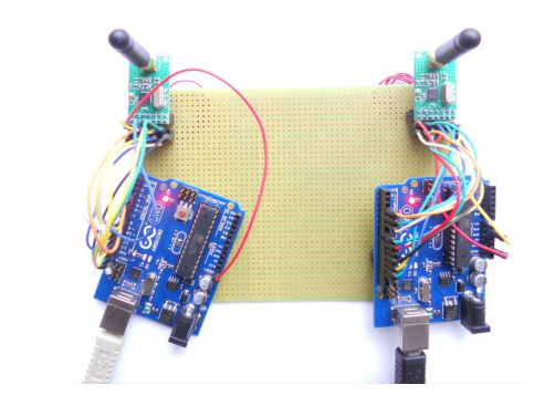
upload the two examples into two arduino boards, one for sending and other one for receiving:

On the receiving end, you should be able to see:
Hi, Arduino 0,
Hi, Arduino 1,
Hi, Arduino 2,
Documentation
- Nrf905 datasheet - File:Product Specification nRF905 v1.5.pdf
- Schematic - File:XL905-51-schematic.pdf
- Demo Code with atmega 16
- Code for arduino

