Microware Radar Sensor
RCWL
Pin Definition
- 3.3V - LDO 3.3V output
- GND - ground
- OUT - outout signal, detect when object move on front
- VIN - power supply in 4-28V
- CDS - enable the IC, when lower than 0.7V, output keep on low TTL signal.
Features
- Voltage 4-28V
- Current 3mA
- Detect distance 5-9M
- Transmit power 20mW
- Output drive capability 100mA
- Output signal 0 or 3.3V
- working temperature -20~80
- storage temperature -40~100
Adjustment
- C-TM: repeat trigger time, default 2S, add capacitor can increase repeat time. The method is checking 9196 IC pin 3 frequency, trigger time T = (1/f) * 32768
- R-GN: detect distance, connector resistor, distanct get short. default 7M. for 1M resistor, detect about 5M.
- R-CDS: internal VCC connect between IC pin CDS and R-CDS pin, via 1M internal resistor. CDS connect photocell, can close sensor on night. You can set R-CDS value by the needs of ambient light.
Use note
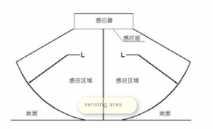
- Should have no any metal on front ot sensing area
- Should keep at least 1CM space free
- sensor and installation better keep parallel.
- sensor front is main sensing area, back side sensing capability is less better
- The sensor can not be implement on same area in the same time, or will have interference. Each should have at least 1 meter gap.


