Latest revision as of 23:01, 31 October 2023
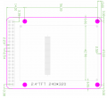
Dimension
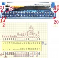
Pins Definition and Wiring
EDL LCDs
- All LCDs are 16bit parallel data
| Size / resolution / color |
Driver
|
| 2.4 - 320*240 - 65K |
ILI9341 <- ILI9325 (New V2.1) <- S6D1121 (Old V1.2)
|
| 3.2 - 320*240 - 65K |
ILI9341 (TFT_320QVT_9341) <- SSD1289 (TFT_320QVT)
|
| 3.2-W - 400*240 - 262K (discountined) |
HX8352
|
| 4.3 - 480*272 - 16M |
SSD1963
|
| 5.0 - 800*480 - 16M |
SSD1963
|
| 7.0 - 800*480 - 16M |
SSD1963
|
- Module the user through the back of the PCB J3 pad set 8/16 bit interface, shorting J3 pad module in 16-bit mode, not less then work in 8-bit mode, module shipments default OPEN, which is shippedThe default is 8-bit interface, 8-bit mode, only 8 (DB8-DB15, DB0-DB7 ground or to unsettled to connect). 8-bit interface occupied IO than 16 interface occupied IO to 8 less, but more slowly, 16-bit interface occupied IO 8 more, but faster).
EDL
- Extra VCC, GND, LEDA (LED back light) also need to connect
- LED_A Pins for the back light of the screen, max volt at 3.2V, connect 20ohm for 3.3V, and 500ohm for 5V, as a current limited purpose.
| LCDs Pins |
Description |
Touch Pin |
Description |
SD Card Pin |
Description
|
| RS |
Data / Command |
D_CLK |
Clock |
SD_SCK |
Clock pin
|
| WR |
Write |
D_CS |
Chip Select |
SD_DIN |
Data in
|
| RD |
Read |
D_DIN |
Data in |
SD_CS |
Chip select
|
| CS |
Chip Select |
D_DOUT |
Data out |
SD_DOUT |
Data out
|
| RST |
Reset |
D_PENIRQ |
Interruppt
|
| D0-D15 |
Data Pin
|
Schematic
Discountined Boards TFT01


