Difference between revisions of "Category:Gerber"
(No difference)
|
Latest revision as of 14:46, 18 July 2023
Common Gerber File Problems
Outline
- For this reason, the manufacture will not how to cut it, even you have all the copper trace, holes, via, etc, correct, but the PCB still won't have a shape, this is impossible for manufacturing.
Drilli Format
- Follow file read in viewmate
- If your file is missing the T01C0.787... etc. It will can not be used.
- These are the drill sizes and are required in the header. Note: some software will include "inline" tool sizes - which means that they are not in the "header" information at the top of the drill file but are scattered through the file just before the tool is used. This is also ok - but they must be somewhere!
- Open your own drill file and check to see that the drill sizes are included at the top of your file. 2.4 trailing is what we use, but any format (2:3 leading, 1:5 none, etc) is OK! If it can be imported, we'll get it imported - however you may notice that the drill file looks strange during the upload since 2:4 is the default for rendering the image.
Gerber View Tool
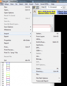
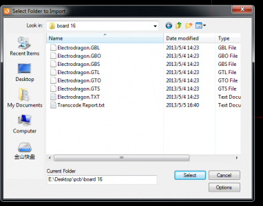
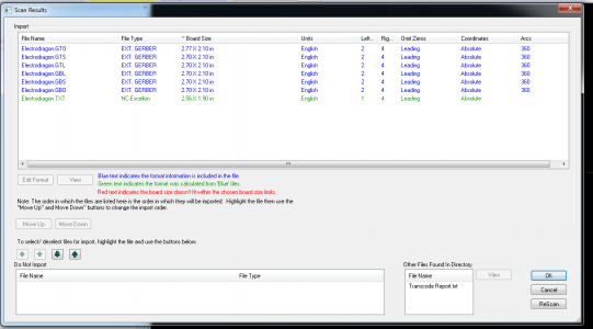
- www.pentalogix.com/viewmate.phpViewmate is best the we like, simply open the software, importing from directory, the tool will automatically read all the gerber files and display. You will need to register on their site to get the serial code when installing the software, if you already have then you can feel free to download from somwhere else like softpedia.
- GC-Prevue, Another freeware Gerber view tool
- The online gerber view - http://mayhewlabs.com/3dpcb.
- zofzPCB - provide very good 3D visualization.
Use with Gerber view
Gerber Required File List
- Signal copper layers: Top layer, Bottom layer, Maybe medium layers optional
- Soldering Stop mask layers: Top and Bottom
- Silk screen layers: Top and Bottom
- Drill layer and Outline (Dimension) mechanical layer:
- Drill drawing: we call the hole character, different holes with different symbols, some still indicated next to the symbol corresponding to the pore diameter and pore number.
- This is used to check the NC drill, and normally for human reading.
- NC drill: we call drill with, see the graphics are solid (as solid round, solid oval), for practical file, and used by machine directly
The Following files are optionally:
- Solder paste : Top and Bottom, Only for making stencil.
Gerber File Extension List
We are only accepting the following file extensions:
| Format | Top & Bottom Copper | Top & Bottom Solder Mask | Top & Bottom Silk | Top & Bottom Solder Paste | NC Drill | Outline / Mech / Keepout Layer |
|---|---|---|---|---|---|---|
| Eagle | cmp+sol | stc+sts | plc+pls | - | drd, + dri* | - |
| Protel | GTL+GBL | GTS+GBS | GTO+GBO | GTP+GBP | txt (or Drl) | GKO, GML or GM1 |
| Orcad | top+bot | smt+smb | sst+ssb | spt+spb | thruhole.tap | - |
Note:
- The "*" file may not very necessary.
- Dri (For eagle) - Drill Station Info File
- Drl (For eagle) - Excellon Tool List
Mre similar files:
- gpi - gerber plot information (not really useful)
- MiddleCopper 1-99
Output Gerber
Animation Tutorial
Gerber Export Settings
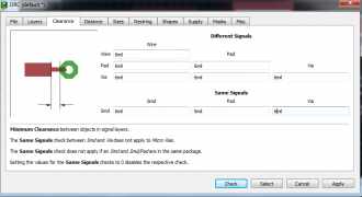
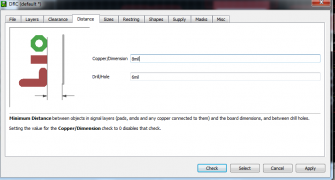
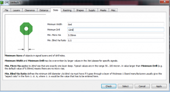
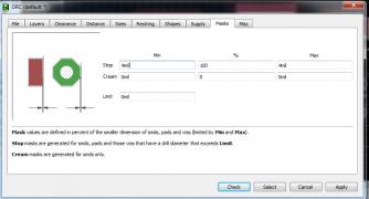
Use the minimal settings in eagle


