Difference between revisions of "TP4056"
(No difference)
|
Latest revision as of 15:42, 13 August 2021
Battery Charge Management - "Smart Charge" IC
TP4056 Specification
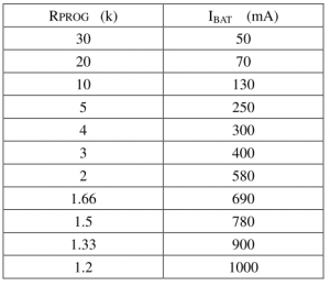
- R4 Prog value setting table, see right table
- Charging Status LEDs
- Module will generate many heat, because when run on high current, module need to step down the votalge from 5V-4.2V, so it is about 0.8V * 1A heat dissipation.
| Status | Charge(CHRG) | Standby(STDBY) |
|---|---|---|
| Charging | ON | OFF |
| Charged | OF | ON |
| Error (battery temperature is too high, too low and other fault conditions, with or without battery access (TEMP use)) | OFF | OFF |
| No battery detected | Blink | ON |
More notification
- 1. The test current ammeter can only be connected in series with the 5V input of the charging board.
- 2. Charging current is the best battery capacity of 0.37C, which is 0.37 times the capacity, such as 1000mAH battery charging current 400 This is enough. Too large charge speed effect is poor, washed out of the battery voltage off more!
- 3. Charging connection wire can not be too thin. This connection resistance. Too thin then washed out the battery voltage dropped more.
- 4. The best connection with the battery contact. Otherwise, the battery voltage off more finished.
- 5. If the 5V input voltage is high, such as 5.2 or even 5.5, will cause the charging current less than 1000mA, this is normal. High voltage chip heat will automatically reduce the charging current, not to the chip burned. It is normal for the chip to generate heat at about 60 degrees at work. After all, charging current.
- 6. Input reverse has no effect on the chip, but the output (battery side) reverse will burn the chip, please note the buyer.
Calculation
I = 1V/1K * 1.2 = 1.2A
- 1K=1.2A
- 3K 400mA
- 10K = 130mA
- 100K = 12mA
