Difference between revisions of "RPI Python"
(No difference)
|
Latest revision as of 11:58, 27 May 2021
Python
Blinking LED
import time
import RPi.GPIO as GPIO
LED = 4               #Physical pin 7, BCM pin GPIO.4 on the BCM2835
GPIO.setmode(GPIO.BCM)
GPIO.setup(LED, GPIO.OUT)
while 1:
GPIO.output(LED, True)
time.sleep(0.5)
GPIO.output(LED, False)
time.sleep(0.5)
Using NRF24L01
Arduino Side
- Download the RF24 library, turn on the arduino IDE, in the example sketches, choose pinpair.
- Wire up your arduino to radio, and make one more wire from digital pin 7 to GND, this is to send the radio to a transmitter.
- replace the loop part, because the RPI code can not read unsigned long data unless you change it.So for demostration, we only send bytes data to RPI as below, you can see here until word "d" in "doing", the length is 32 bytes.
void loop(void)
{
    // transmit and increment the counter
    radio.write("Hi, Electrodragon, How are you doing?", 32);
    // pause a second
    delay(1000);
}
RPI side
RPI initiation
- turn on the SSH and sudo firstly
sudo su
- Load SPI for RPI
modprobe spi_bcm2708
modprobe spidev
Downloading demo sketch and library
- turn the following commands (make sure installed git):
git clone https://github.com/stanleyseow/RF24.git
cd RF24/librf24-rpi/librf24/examples/
make
- (optional) you can move the librf24 subfolder out from the main folder, since it is the only folder we will use here, so you can do
cd RF/librf24-rpi
mv librf24 /home/pi // move to the pi default folder
rm librf24 rf // rename it to rf
Editing demo sketch rpi-hub.cpp
navigate to examples folder in librf24 folder
cd examples
nano rpi-hub.cpp
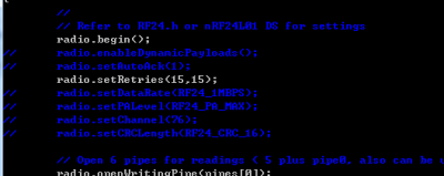
for the demo sketch, please change (optional), comment the following settings, this is not very necessary.
Now the final step is complie it
make
Running, reference
- run the bash command, now you can see the data printing on
./rpi-hub
- reference link
- Demo video (not yet updated)
Display: 1602 LCD
- Install the python necessary packages, see the next section
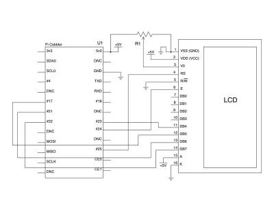
- wiring the pi to the 1602 LCD as below
- Get the python library by command:
git clone https://github.com/adafruit/Adafruit-Raspberry-Pi-Python-Code.git
- If you're using a Version 2 Raspberry Pi, pin #21 has been replaced with pin #27 so edit Adafruit_CharLCD.py and change:
def __init__(self, pin_rs=25, pin_e=24, pins_db=[23, 17, 21, 22], GPIO = None):
to
def __init__(self, pin_rs=25, pin_e=24, pins_db=[23, 17, 27, 22], GPIO = None):
- Run the testing code
chmod +x Adafruit_CharLCD.py
sudo ./Adafruit_CharLCD.py
- One more example to display the ethernet IP address:
#!/usr/bin/python

from Adafruit_CharLCD import Adafruit_CharLCD
from subprocess import *
from time import sleep, strftime
from datetime import datetime

lcd = Adafruit_CharLCD()

cmd = "ip addr show eth0 | grep inet | awk '{print $2}' | cut -d/ -f1"

lcd.begin(16,1)

def run_cmd(cmd):
        p = Popen(cmd, shell=True, stdout=PIPE)
        output = p.communicate()[0]
        return output

while 1:
        lcd.clear()
        ipaddr = run_cmd(cmd)
        lcd.message(datetime.now().strftime('%b %d  %H:%M:%S\n'))
        lcd.message('IP %s' % ( ipaddr ) )
        sleep(2)
Driving Stepper Motor (using IC LD293D)
import RPi.GPIO as GPIO
import time

GPIO.setmode(GPIO.BCM)

enable_pin = 18
coil_A_1_pin = 4
coil_A_2_pin = 17
coil_B_1_pin = 23
coil_B_2_pin = 24

GPIO.setup(enable_pin, GPIO.OUT)
GPIO.setup(coil_A_1_pin, GPIO.OUT)
GPIO.setup(coil_A_2_pin, GPIO.OUT)
GPIO.setup(coil_B_1_pin, GPIO.OUT)
GPIO.setup(coil_B_2_pin, GPIO.OUT)

GPIO.output(enable_pin, 1)

def forward(delay, steps):
  for i in range(0, steps):
    setStep(1, 0, 1, 0)
    time.sleep(delay)
    setStep(0, 1, 1, 0)
    time.sleep(delay)
    setStep(0, 1, 0, 1)
    time.sleep(delay)
    setStep(1, 0, 0, 1)
    time.sleep(delay)

def backwards(delay, steps):
  for i in range(0, steps):
    setStep(1, 0, 0, 1)
    time.sleep(delay)
    setStep(0, 1, 0, 1)
    time.sleep(delay)
    setStep(0, 1, 1, 0)
    time.sleep(delay)
    setStep(1, 0, 1, 0)
    time.sleep(delay)


def setStep(w1, w2, w3, w4):
  GPIO.output(coil_A_1_pin, w1)
  GPIO.output(coil_A_2_pin, w2)
  GPIO.output(coil_B_1_pin, w3)
  GPIO.output(coil_B_2_pin, w4)

while True:
  delay = raw_input("Delay between steps (milliseconds)?")
  steps = raw_input("How many steps forward? ")
  forward(int(delay) / 1000.0, int(steps))
  steps = raw_input("How many steps backwards? ")
  backwards(int(delay) / 1000.0, int(steps))
Driving DC Motor, Servo using L293D
====direct soft GIPO.PWM control for servo
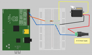
- Use soft GPIO.PWM control servo, and GUI interface, wiring the servo as image here, a 1K resistor added between the RPI IO and servo signal pin(for limiting current and protect RPI GPIO).
- check the demo code on GUI section belwo (also comments added).
- It is pretty simple one IO control.(reference link: http://razzpisampler.oreilly.com/ch05.html)
Other methods
- Adafruit has other method but need to install new OS.
- Using raspirobot board, see the tutorial here
Installing Python packages
sudo apt-get install python-dev (may skip)
sudo apt-get install python-setuptools (may skip)
sudo easy_install -U distribute (may skip)
sudo apt-get install python-pip
sudo pip install rpi.gpio
sudo apt-get install python-serial (Install the serial terminal)
- type python to enter into python command mode.
Python GUI programming on RPI
It is no need to install Tkinter on RPI, type following command to test
python // to enter into python IDLE
import Tkinter (T is cap on 2.6 version, but t in new 3.0+ version)
If shows error that module is not installed, run install
sudo apt-get install python-tk
Demo code to run soft PWM control for servo
use nano to edit, copy and paste the following code, save this file at /home/pi/x.py
from Tkinter import *
import RPi.GPIO as GPIO
import time

GPIO.setmode(GPIO.BCM)
GPIO.setup(18, GPIO.OUT)
pwm = GPIO.PWM(18, 100) // where 18 is the channel GPIO, and 100 is the hz
pwm.start(5) // 5 is the duty at start

class App:

    def __init__(self, master):
        frame = Frame(master)
        frame.pack()
        scale = Scale(frame, from_=0, to=180,
              orient=HORIZONTAL, command=self.update) // it can scroll from 0 to 180, orientation is horizontal, and run the next function self.update
        scale.grid(row=0)


    def update(self, angle):
        duty = float(angle) / 10.0 + 2.5 // calculate the duty
        pwm.ChangeDutyCycle(duty) // then change the duty

root = Tk()
root.wm_title('Servo Control')
app = App(root)
root.geometry("200x50+0+0") // set the windows size 200x50, and initiated position 0 and 0
root.mainloop()
Run the test
Turn on VNC for RPI, let the VNC choose automatic resolution, open LXterminal, and run the following command gksudo python /home/pi/x.py
RPI with IIC and using MCP2300xx as IO expander
Installing IIC
- The following setup can be done in advance setting of raspi-config, just run sudo raspi-config
- The new Raspbian distro already have the I2C driver installed but they are disabled by default. To enable it all you need to do is comment out a line by putting # in front. At the prompt type: sudo nano /etc/modprobe.d/raspi-blacklist.conf
then add a # on the 3rd line.
- Next edit the modules file by: sudo nano /etc/modules
Add i2c-dev to a new line.
- Now install the i2c-tools package by: sudo apt-get install i2c-tools
- Now add a new user to the i2c group: sudo adduser pi i2c
If your board is the Rev 2 type this: sudo i2cdetect -y 1
You should see something like this:
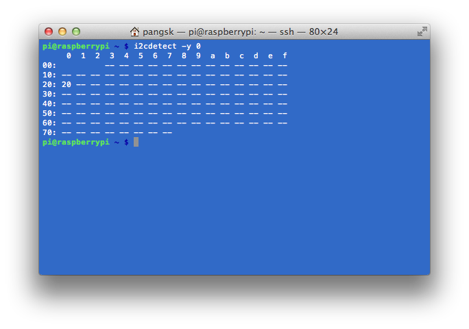
in the output, row on "0", and column "20" means the IIC address is 0x20
- Next install the python-smbus python module: sudo apt-get install python-smbus
Now you are ready to use the i2c with python.
- See the example using RPI relay shield page, board using MCP23008 as an expander.
Python Programming
- Turn IO 7 ON
import RPi.GPIO as GPIO ## Import GPIO library
GPIO.setmode(GPIO.BOARD) ## Use board pin numbering
GPIO.setup(7, GPIO.OUT) ## Setup GPIO Pin 7 to OUT
GPIO.output(7,True) ## Turn on GPIO pin 7
- Blink LED
import RPi.GPIO as GPIO ## Import GPIO library
import time ## Import 'time' library. Allows us to use 'sleep'

GPIO.setmode(GPIO.BOARD) ## Use board pin numbering
GPIO.setup(7, GPIO.OUT) ## Setup GPIO Pin 7 to OUT

## Define a function named Blink()
def Blink(numTimes,speed):
for i in range(0,numTimes):## Run loop numTimes
print "Iteration " + str(i+1)## Print current loop
GPIO.output(7,True)## Switch on pin 7
time.sleep(speed)## Wait
GPIO.output(7,False)## Switch off pin 7
time.sleep(speed)## Wait
print "Done" ## When loop is complete, print "Done"
GPIO.cleanup()

## Ask user for total number of blinks and length of each blink
iterations = raw_input("Enter total number of times to blink: ")
speed = raw_input("Enter length of each blink(seconds): ")

## Start Blink() function. Convert user input from strings to numeric data types and pass to Blink() as parameters
Blink(int(iterations),float(speed))
