Difference between revisions of "SX1278 HDK"
(No difference)
|
Latest revision as of 19:05, 8 May 2021
Features
Main features
- SPI Interface
- central frequency 433mhz, or 470mhz
- referencial distance 10KM
- SX1278 IC, TTL output
- Max power rate 20dbm, can be setup by software
- 1.7-3.8V power supply
Specfication
- Operating voltage: 1.8 ~ 3.7V
- Receiving current: 10 ~ 14mA
- Tranmission current:
- 120 mA @ + 20 dBm
- 90mA @ + 17dBm
- 29mA @ + 13dBm
- Operating frequency: 433MHz, 475MHz
- Transmit power: +20 dBm
- Receiver sensitivity:
- -139dBm @ LoRaTM & 62.5Khz & SF = 12 & 146bps
- -136 @ LoRaTM & 125Khz & SF = 12 & 293bps
- -118 @ LoRaTM & 125Khz & SF = 6 & 9380bps
- -123@FSK&5Khz&1.2Kbps
- -117@FSK&5Khz&4.8Kbps
- -110@FSK&20Khz&38.4Kbps
- Frequency error: +/- 10ppm
- FIFO space: 64 bytes
- Data rate:
- 1.2K~300Kbps@FSK
- 0.018K ~ 37.5Kbps @ LoRaTM
- Modulation: FSK, GFSK, MSK, GMSK, LoRaTM, OOK
- Interface type: SPI
- Sleep Current: 0.2uA@SLEEP, 1.5uA @ IDLE
- Operating temperature: -40 ℃ ~ +85 ℃
- Digital RSSI function
- Automatic frequency correction
- Automatic Gain Control
- RF wake-up function
- Low voltage detection and temperature sensors
- Fast wake-up and frequency hopping
- Highly configurable packet handlers
- Antenna diversity and TX / RX switch control
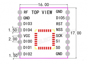
Pin definition, size
- 1 GND - Negative power ground
- 2 SO I SPI interface MISO data output
- 3 SI O SPI interface MOSI data input
- 4 SCK I SPI interface SCLK clock input
- 5 NSS I SPI Interface NSS Select input
- 6 RESET I Reset pin
- 7 DIO5 I / O direct connect chip DIO5 digital I / O pin, software setting
- 8 GND - Negative power ground
- 9 RF I / O RF signal input / output, connected to 50Ω antenna
- 10 GND - Negative power ground
- 11 DIO3 I / O direct connect chip DIO3 digital I / O pin, software setting
- 12 DIO4 I / O direct connect chip DIO4 digital I / O pin, software setting
- 13 VCC - positive power supply 1.8 ~ 3.7V
- 14 DIO0 I / O direct connect chip DIO0 digital I / O pin, software setting
- 15 DIO1 I / O direct connect chip DIO1 digital I / O pin, software setting
- 16 DIO2 I / O Direct Connect DIO2 Digital I / O pin, software setting
LORA Modules
EE1 Lora Module 100mW
Pin Definition
- GND - negative ground
- SDO 0 SPI Interface MISO Data Output
- SDI I SPI Interface MOSI Data Input
- SCK I SPI Interface SCLK Clock Input
- SEL I SPI Interface NSS Select Input
- RST I/O reset pin
- IO5 I/O Direct Chip DIO5 Digital I/O Pin, Software Set
- GND - negative ground
- ANT I/O RF Signal Input/Output with 50Ω Antenna
- GND - negative ground
- IO3 I/O Direct Connect Chip DIO3 Digital I/O Pin, Software Setup
- IO4 I/O Direct Connect Chip DIO4 Digital I/O Pin, Software Setup
- VCC - Positive Power Supply 1.8 to 3.7V
- IO0 I/O directly connected to the chip DIO0 digital I/O pin, software setting
- IO1 I/O Direct connection to chip DIO1 digital I/O pin, software setting
- IO2 I/O Direct Connect Chip DIO2 Digital I/O Pin, Software Setup
Specification
- Interface form: SPI
- Sleep current: 0.2uA@SLEEP, 1.5uA@IDLE
- Working temperature: -40°C~+85°C
- Digital RSSI function
- Automatic frequency correction
- Automatic gain control
- RF wake up function
- Low voltage detection and temperature sensor
- Fast wake-up and frequency hopping
- Highly configurable packet handler
- Antenna diversity and TX/RX switch control
- Size: 16*16*2.7mm, including plate thickness 1mm
- Operating voltage: 1.8 to 3.7V
- Receiving current: 10~14mA
- Send current: 120mA@+20dBm, 90mA@+17dBm, 29mA@+13dBm
- Operating frequency: 433MHz, 470MHz
- Transmission power: +20dBm
- Receiving sensitivity:
-139dBm@ LoRa TM &62.5Khz&SF=12&146bps
-136@LoRa TM &125Khz&SF=12&293bps
-118@LoRa TM &125Khz&SF=6&9380bps
-123@FSK&5Khz&1.2Kbps
-117@FSK&5Khz&4.8Kbps
-110@FSK&20Khz&38.4Kbps
- Frequency error: +/-10ppm
- FIFO space: 64Byte
- Data rate:
1.2K to 300Kbps@FSK
0.018K~37.5Kbps@ LoRa TM
Modulation: FSK, GFSK, MSK, GMSK, LoRaTM, OOK
EE2 Lora Module 1W
| Version | 433 | 868 | 915 | 170 |
|---|---|---|---|---|
| Frequency | 410~441mhz | 862~893mhz | 900~931mhz | 160~173.5mhz |
| Feature | ISM - Asia | EU | America | High peneration |
| Chip | SX1278 | SX1276 | SX1276 | SX1278 |
| Power | 30dBm (1W) | 30dBm (1W) | 30dBm (1W) | 30dBm (1W) |
| Distance | 8Km | 8Km | 8Km | 8Km |
| Communication | UART | UART | UART | UART |
| Footprint and Size | 43*24 mm DIP | 43*24 mm DIP | 43*24 mm DIP | 43*24 mm DIP |
| Current | 610 mA | 680 mA | 700 mA | 680 mA |
| Voltage | 3.3-5.2VDC | 3.3-5.2VDC | 3.3-5.2VDC | 3.3-5.2VDC |
| Baud rate | 1200-115200 | 1200-115200 | 1200-115200 | 1200-115200 |
| On Air speed | 0.3-19.2kbps | 0.3-19.2kbps | 0.3-19.2kbps | 0.3-19.2kbps |
| Transmission length | 512 bytes | 512 bytes | 512 bytes | 512 bytes |
| Sensitivity | [email protected] | [email protected] | [email protected] | [email protected] |
Working Mode
- M0/M1 - 0/0 - normal mode
- M0/M1 - 1/0 - wake up on air from transitter mode, auto add wake code
- M0/M1 - 0/1 - wake up on air from receiver mode, can not send in this mode
- M0/M1 - 1/1 - sleep mode, also enter into config mode


