EY-08 Hardware
(Redirected from EB08)
Quick Start and Notice
About AT Commands
- AT commands at default rate 115200
- Commands no need \r\n
- AT+PASS123456 to set password to 123456, AT+MAC to check mac address: +MAC:A81B6A85C841
- Module in AT Commands mode when NOT connected. And enter into data transmission mode when it paired.
About Pairing
- No need to pair, set working mode and use directly
- master module can only allow one slave module connect.
About Sleep Mode
- Pull P00 to low to wake up the module from sleep mode, then module can accept data tranmission. This pin is internal pull up.
About hardware design.
- Power supply must use 3.3 or 3V for final products
About Features
- in room distance is 15-30 meters, max to 60 meters.
- Tranmission data speed is 1KB/s
- Do not support 2.0 or 3.0 bluetooth version.
Features Modes
- Slave transmission data mode, APP tranmission mode
- Wechat tranmission mode
- iBeacon mode ( wechat shake or iBeacon mode )
- Sensor mode
- Master sensor mode
- Master observation mode
- PWM, RTC or IO control (command from host MCU or BLE data )
- iBeacon indoor location mode RTC
- Support LED product, vibration product mode
Characters
- Tested on 3V3
- write data to support hundreds of bytes to write (for example, 512 bytes)
- Transmission distance 15 - 30 meters
| Operating mode | state | current |
|---|---|---|
| Slave Transmission Mode | Connected / Not Connected / Standby | 0.8mA / 300uA / 1uA |
| Slave Broadcast mode (IBeacon, sensor) | 0.5mA / 300uA / 1uA | |
| Host Transmission Mode | Connection / Not connected / Standby | 20mA / 9mA / 1uA |
| Host observer mode (Sensor) | Connection / Not connected / Standby | 9mA |
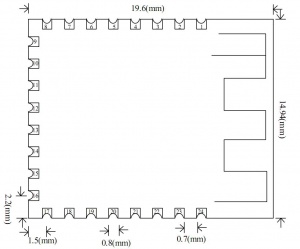
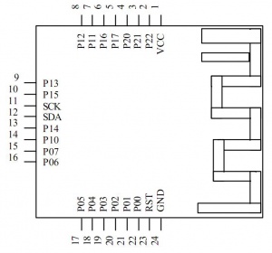
Dimension, Pin definition
- Pin definition
| Pin Number | Definition | Function | Note |
|---|---|---|---|
| 1 | VCC | Power Supply | 3V or 3.3V |
| 2 | P22 | - | |
| 3 | P21 | - | |
| 4 | P20 | - | |
| 5 | P17 | - | |
| 6 | P16 | Bluetooth Status | LOW - Connected |
| 7 | P11 | PWM2 | control by APP |
| 8 | P12 | IO1 | control by APP |
| 9 | P13 | IO2 | control by APP |
| 10 | P15 | IO3 | control by APP |
| 11 | SCK | Example | |
| 12 | SDA | Example | |
| 13 | P14 | IO4 | control by APP |
| 14 | P10 | PWM1 | |
| 15 | P07 | PWM3 | |
| 16 | P06 | PWM4 | |
| 17 | P05 | NC in new version (RTC Alarm IO) | Boardcasting status LED, IO output low when the RTC timing time expires |
| 18 | P04 | NC in new version (RTC Alarm IO) | IO output low when the RTC timing time expires |
| 19 | P03 | TXD | serial |
| 20 | P02 | RXD | serial |
| 21 | P01 | - | AT commands mode, normally high, when connected turn to low, but can push to high for sending at commands when connected |
| 22 | P00 | PWRC - module sleep wake-up pin |
|
| 23 | RST | Resets the hardware reset pin | |
| 24 | GND | Power ground |
Sleep Mode and Power Saving
- Command AT+SLEEP to put into sleep mode
- User can pull Pin00 down to wake up.
- default 100ms boadcasting current comspution is 500uA, 300ms is less than 100uA, in sleep mode no need boarcasting is 1uA
- Wake up BLE, then wake up MCU via BLE, will save power better
Breakout Board NBL1061
- PWRC - P00 wake up pin
- STAT - P16 bluetooth status
- LED - P05 Bluetooth boardcasting LED
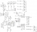
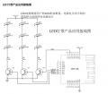
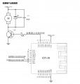
Schematic of Reference design
For sleep mode
- P00 is wake-up pin, pull down to wake up after use send at+sleep
- P05 - broadcasting pin, blink when broadcasting
- P16 - Connection Status, TTL can be reversed
- P01 - normally low, when connected can still pull to low to enter into AT commands mode
