Voltmeter Ammeter
(Redirected from DC Digital Current Meter Ammeter 10A)
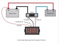
Wiring of digital current meter
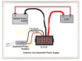
Use sperated Power w/o shunt
Use sperated Power (another)
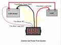
Use Power from system
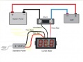
Use seperated power w shunt
Use system load power w shunt


Voltmeter + Ammeter
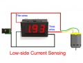
- Red thin wire (VCC): Power input+, 3.5-30V(NOTE: If the measuring signal is lower than 30V and have abundant power supply, it can be used as power supply for the module [black wire and yellow wire are contacted together to use])
- Black thin wire(GND): Power input-, Measurement signal - 3.5-30V
- Yellow thin wire (VIN): Measurement signal+ (0-100V)
- Red thick wire (I+): Current input+ (connect to load negative)
- Black thin wire(I-): Current input- (connect to power supply negative in series)
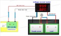
Voltage current meter with isolated power supply
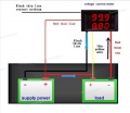
Voltage current meter in the measurement system for power supply 02


Calibration of Version R1
- Error phenomenon one:Because of the some eclectic parts ageing and influenced by the temperature, sometimes when measuring the small current, the error of some meter become big or sometimes some meter don?t show zero without load.
- Solution:When the meter is off the power, please short circuit A and B (connect A and B). Then make the meter have the electricity, the meter will automatically calibrated to zero. When the automatic calibration is over, please disconnect A and B. After this, that is ok.
- Error phenomenon two:Because of the some eclectic parts ageing and influenced by the temperature, sometimes when measuring big current, the error of some meter become big.
- Solution:let the meter show about half of the range (for example: range 0-10A, let meter show about 5A). At the meaning time, you adjust R7 until the meter show the value is same to the value the more digit meter show.
Wiring of Current Meter With Shunt
Schematic
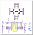
Voltmeter by MCU
