1602 LCD
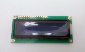
1602 Display
Pin Definition
- pin1 --- (GND)
- pin2 --- (VDD)
- pin3 --- (Display Contrast Bias, + resistor 1.5K-2.2K)
- pin 4 (RS) --- Command / Data Selection
- pin 5 (R/W) --- Read / Write Selection
- pin 6 (Enable) --- Enable
- D0-D7 --- Data Pins
- BLA --- Back light positive
- BLK --- Back Light negative
1602 LCD using PCF8574 IO expander
Usage
- A4 - SDA
- A5 - SDL
- A-VCC: Connect for blacklight
- I2C Address, set the IIC Address, default is 0X27
Demo Code and library
- Arduino Demo Code
- https://github.com/marcoschwartz/LiquidCrystal_I2C
- Download from github library, arduino library has "only display one character" issue
Schematic
Use with MCP23008 IO expander
Introduction
LCDs are a fun and easy way to have your microcontroller project talk back to you. Character LCDs are common, and easy to get, available in tons of colors and sizes.But it find that the number of pins necessary to control the LCD can be restrictive, especially with ambitious projects.
The common charctic LCD need more than 6 pins for controlling. With the limited pin resources, your project may be out of resources using normal LCD shield. Here we provide the IIC LCD module, you only need 2 lines (I2C) to display the information.
By using simple i2c and SPI input/output expanders we have reduced the number of pins (only 2 pins are needed for i2c) while still making it easy to interface with the LCD.
Features
- Supply voltage: +5 V
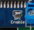
- Supports two protocols IIC/I2C and SPI
- With backlight and contrast adjustment potentiometer
- Including IIC and SPI Terminals, you can use ordinary wires to connect, do not need to purchase a special adapter cable, convenient for enthusiasts.
- Work with any 'standard'16x2 character LCD
- LCD Display Mode: STN, Positive, Transflective
- Display Color: Deep Blue/ Yellow Green
- Viewing Angle: 6H
- Outline Dimension: 80*36*15.8 MAX
How it looks
Schematic
Pin definition and Rating
- IIC Pin definition
| Pin | # | Pad Type | Description |
|---|---|---|---|
| GND | 1 | VSS | Ground port |
| VCC | 2 | 3.3V | Integrated 3.3V(+)supply with on-chip linear regulator output within 3.15-3.3V |
| SDA | 3 | Data | Data |
| SCL | 4 | Clock | Clock |
- SPI Pin definition
| Pin | # | Pad Type | Description |
|---|---|---|---|
| GND | 1 | VSS | Ground port |
| VCC | 2 | 3.3V | Integrated 3.3V(+)supply with on-chip linear regulator output within 3.15-3.3V |
| C | 3 | Clock | Clock |
| D | 4 | Data | Data |
| L | 5 | Latch | Latch |
Programming
IIC mode connect the CLK pin to Analog 5 (i2c SCL pin) and DAT to Analog 4 (i2c SDA pin). Connect the 5V and ground pins to respective power pins.
SPI mode connect the CLK pin to Digital 2 (SPI Clock pin) and D to Digital 3 (SPI DATA pin) and L to Digital 4 (SPI Latch pin). Connect the 5V and ground pins to respective power pins.
The Library is base on Adafruit's IICLibrary, we had accorded our hardware do the appropriate changes. And you can easy choose SPI mode or IIC mode by the Switch
Includes important code snippet. Demo code like :
IIC Mode
/*
 Demonstration sketch for Adafruit i2c/SPI LCD backpack
 using MCP23008 I2C expander
 ( http://www.ladyada.net/products/i2cspilcdbackpack/index.html )

 This sketch prints "Hello World!" to the LCD
 and shows the time.

  The circuit:
 * 5V to Arduino 5V pin
 * GND to Arduino GND pin
 * CLK to Analog #5
 * DAT to Analog #4
*/

// include the library code:
#include <Wire.h>
#include <LiquidCrystal.h>

// Connect via i2c, default address #0 (A0-A2 not jumpered)
LiquidCrystal lcd(0);

void setup() {
  // set up the LCD's number of rows and columns:
  lcd.begin(16, 2);
  // Print a message to the LCD.
  lcd.print("hello, world!");
}

void loop() {
  // set the cursor to column 0, line 1
  // (note: line 1 is the second row, since counting begins with 0):
  lcd.setCursor(0, 1);
  // print the number of seconds since reset:
  lcd.print(millis()/1000);

  lcd.setBacklight(HIGH);
  delay(500);
  lcd.setBacklight(LOW);
  delay(500);
}
SPI Mode
/*
 Demonstration sketch for Adafruit i2c/SPI LCD backpack
 using 74HC595 SPI expander
 ( http://www.ladyada.net/products/i2cspilcdbackpack/index.html )

 This sketch prints "Hello World!" to the LCD
 and shows the time.

  The circuit:
 * 5V to Arduino 5V pin
 * GND to Arduino GND pin
 * CLK to Digital 2
 * DAT to Digital 3
 * LAT to Digital 4
*/


// include the library code:
#include <Wire.h>
#include <LiquidCrystal.h>

// Connect via SPI. Data pin is #3, Clock is #2 and Latch is #4
LiquidCrystal lcd(3, 2, 4);

void setup() {
  // set up the LCD's number of rows and columns:
  lcd.begin(16, 2);
  // Print a message to the LCD.
  lcd.print("hello, world!");
}

void loop() {
  // set the cursor to column 0, line 1
  // (note: line 1 is the second row, since counting begins with 0):
  lcd.setCursor(0, 1);
  // print the number of seconds since reset:
  lcd.print(millis()/1000);

  lcd.setBacklight(HIGH);
  delay(500);
  lcd.setBacklight(LOW);
  delay(500);
}
1602 LCD + Keypad Shield
Introduction
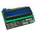
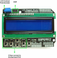
The LCD Keypad shield is developed for Arduino compatible boards, to provide a user-friendly interface that allows users to go through the menu, make selections etc. It consists of a 1602 white character blue backlight LCD. The keypad consists of 5 keys — select, up, right, down and left. To save the digital IO pins, the keypad interface uses only one ADC channel. The key value is read through a 5 stage voltage divider.
Pin Allocation
- Analog 0 - Button (select, up, right, down and left), DO NOT use this pin
- Digital 4 - 7 - DB 4 - 7
- Digital 8 - RS (Data or Signal Display Selection)
- Digital 9 - Enable
- Digital 10 - Backlight Control
Arduino demo code
Demo Code using button functions
 #include <SPI.h>  // Add a import library line if you get error message:
#include <LiquidCrystal.h>

LiquidCrystal lcd(8, 9, 4, 5, 6, 7);           // select the pins used on the LCD panel

// define some values used by the panel and buttons
int lcd_key     = 0;
int adc_key_in  = 0;

#define btnRIGHT  0
#define btnUP     1
#define btnDOWN   2
#define btnLEFT   3
#define btnSELECT 4
#define btnNONE   5

int read_LCD_buttons(){               // read the buttons
    adc_key_in = analogRead(0);       // read the value from the sensor

    // my buttons when read are centered at these valies: 0, 144, 329, 504, 741
    // we add approx 50 to those values and check to see if we are close
    // We make this the 1st option for speed reasons since it will be the most likely result

    if (adc_key_in > 1000) return btnNONE;

    // For V1.1 us this threshold
    if (adc_key_in < 50)   return btnRIGHT;
    if (adc_key_in < 250)  return btnUP;
    if (adc_key_in < 450)  return btnDOWN;
    if (adc_key_in < 650)  return btnLEFT;
    if (adc_key_in < 850)  return btnSELECT;

   // For V1.0 comment the other threshold and use the one below:
   /*
     if (adc_key_in < 50)   return btnRIGHT;
     if (adc_key_in < 195)  return btnUP;
     if (adc_key_in < 380)  return btnDOWN;
     if (adc_key_in < 555)  return btnLEFT;
     if (adc_key_in < 790)  return btnSELECT;
   */

    return btnNONE;                // when all others fail, return this.
}

void setup(){
   lcd.begin(16, 2);               // start the library
   lcd.setCursor(0,0);             // set the LCD cursor   position
   lcd.print("Push the buttons");  // print a simple message on the LCD
}

void loop(){
   lcd.setCursor(9,1);             // move cursor to second line "1" and 9 spaces over
   lcd.print(millis()/1000);       // display seconds elapsed since power-up

   lcd.setCursor(0,1);             // move to the begining of the second line
   lcd_key = read_LCD_buttons();   // read the buttons

   switch (lcd_key){               // depending on which button was pushed, we perform an action

       case btnRIGHT:{             //  push button "RIGHT" and show the word on the screen
            lcd.print("RIGHT ");
            break;
       }
       case btnLEFT:{
             lcd.print("LEFT   "); //  push button "LEFT" and show the word on the screen
             break;
       }
       case btnUP:{
             lcd.print("UP    ");  //  push button "UP" and show the word on the screen
             break;
       }
       case btnDOWN:{
             lcd.print("DOWN  ");  //  push button "DOWN" and show the word on the screen
             break;
       }
       case btnSELECT:{
             lcd.print("SELECT");  //  push button "SELECT" and show the word on the screen
             break;
       }
       case btnNONE:{
             lcd.print("NONE  ");  //  No action  will show "None" on the screen
             break;
       }
   }
}
Demo Code Using A1 pin to read temperature from sensor LM35
#include <LiquidCrystal.h>

LiquidCrystal lcd(8, 9, 4, 5, 6, 7);        // select the pins used on the LCD panel

unsigned long tepTimer ;

void setup(){
    lcd.begin(16, 2);                       // start the library
}

void loop(){
    lcd.setCursor(0, 0);                   // set the LCD cursor   position
    int val;                               // variable to store the value coming from the analog pin
    double data;                           // variable to store the temperature value coming from the conversion formula
    val=analogRead(1);                     // read the analog in value:
    data = (double) val * (5/10.24);       // temperature conversion formula

    if(millis() - tepTimer > 500){         // output a temperature value per 500ms
             tepTimer = millis();

             // print the results to the lcd
             lcd.print("T: ");
             lcd.print(data);
             lcd.print("C");
     }
}
How to use LiquidCrystal library
Function Explanation
LiquidCrystal(rs, enable, d4, d5, d6, d7) - Creates a variable of type LiquidCrystal. The display can be controlled using 4 or 8 data lines. If the former, omit the pin numbers for d0 to d3 and leave those lines unconnected. The RW pin can be tied to ground instead of connected to a pin on the Arduino; if so, omit it from this function's parameters. for example:
LiquidCrystal lcd(8, 9, 4, 5, 6, 7);
lcd.begin(cols, rows) - Initializes the interface to the LCD screen, and specifies the dimensions (width and height) of the display. begin() needs to be called before any other LCD library commands.for example:
lcd.begin(16, 2);
lcd.setCursor(col,row) - Set the location at which subsequent text written to the LCD will be displayed. for example:
lcd.setCursor(0,0);
lcd.print(data) - Prints text to the LCD.for example:
lcd.print("hello, world!");
lcd.write(data) - Write a character to the LCD.
More function can see:
Resources
LCD2USB
- Based on original project here
- Upload firmware by:
avrdude -c stk200 -p atmega8 -U lfuse:w:0x9f:m -U hfuse:w:0xc9:m -U flash:w:firmware-avrusb.hex
- install driver libusb-win32 in windows
- Hardware shematic please see here.


