Difference between revisions of "ESP Relay Board VDC"
| Line 36: | Line 36: | ||
| Green Out Input Terminal || VIN 5-26V (top / inside of the board), ground (close to the edge outside of the board) || - | | Green Out Input Terminal || VIN 5-26V (top / inside of the board), ground (close to the edge outside of the board) || - | ||
|} | |} | ||
Revision as of 15:13, 22 April 2024
Update Log for ESP Relay Board VDC
Latest version of ESP Relay Board VDC version V4.2
(Old version)
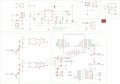
Schematic
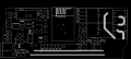
VDC Relay board latest silk print 4.2


- V4.2 added voltage divider on back side of PCB, this need to be soldered manually.
- V4.1 pin headers changed to two group. RST, ADC and DHT_IO16 pins on left side now.
Analag Input A0
| Back Side Jumper | Header text |
|---|---|
| Connect | No voltage divider, A0 directly connect to ESP-12 Module ADC pin. |
| Disconnect | A0 input via voltage divider to ADC = 220K / 100K, maximium input A0 3.3V |
- Reference calculation see here: https://learn.sparkfun.com/tutorials/voltage-dividers/all
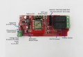
Specific for Relay Board VDC
| Jumper | Header text | Header text |
|---|---|---|
| U2 | wireless RF receiver, output TTL signal to ESP12F pins, DO -> IO2, D1 -> IO15 | - |
| JP2 | Alternative power supply pin 5V-24V, = terminal power input | - |
| JP7 | Power input selection, choose between 5V or 5-24V. | - |
| JP1 | DHT, ADC, RST | - |
| JP6 | row 1: RXD, TXD, 5V, GND, row 2: 3.3V, IO4, IO5, IO15 | - |
| Green Out Input Terminal | VIN 5-26V (top / inside of the board), ground (close to the edge outside of the board) | - |