Category:L298
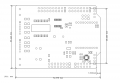
All Boards Reference Schematic
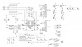
Arduino L298N Module Shield
Arduino L298N Module Shield 02
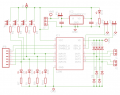
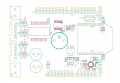
Arduino self-balancing stablizer shield
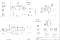
Arduino motor shield schematic R3


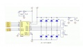
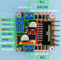
L298N Drive Module
Arduino Demo Code
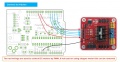
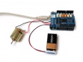
Arduino Wiring
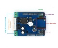
Board pins
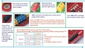
CSA, CSB and 5V-EN jumper
Product Details of R2-C


Note for Use R2 Version
- When you drive voltage (the figure identified as 12V input, can accept the actual input range is 7-12V) to 7V-12V, they can enable the on-board 5V logic supply
- when using the onboard 5V power supply interface, the voltage of + 5V power supply do not be used as input, but can use as output 5V
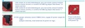
- When the drive voltage is higher than 12V, less than or equal 24V (chip can support manual proposes to 35V, but according to the experience of the general application of a conservative 298 to 24V maximum voltage support has been very great!), For example, to drive a motor rated voltage of 18V. First, you must unplug the onboard 5V output enable jumper caps. And then supply 5V into the output port.
- 5V enables a level of control that is 5V signal when the signal input is active, and the power supply is normal, the motor drive module motor drive module output current. Otherwise, even if the power supply is normal, and no current to the motor. L298N internal voltage logic circuitry. (This is a high-voltage driver unconventional application!)
Drive DC Motor
L298N Can driver 2 channel DC motor, stepper motor, EN, IN1 and IN2 is active on high level.
- EN can be used PWM to move step by step
- IN1 and IN2 can be used to control direction
| ENA | IN1 | IN2 | Motor Status |
|---|---|---|---|
| 0 | x | x | stop |
| 1 or PWM | 0 | 0 | brake |
| 1 or PWM | 0 | 1 | clockwise turn |
| 1 or PWM | 1 | 0 | counter clockwise turn |
| 1 or PWM | 1 | 1 | brake |
Arduino Motor Shield R3
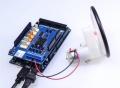
Board Wiring


Arduino Self-balancing Stabilizer Shield
Pin Map
| Arduino Pin | Description |
| D0 | D0 |
| D1 | D1 |
| D2 | CNTA1 |
| D3 | CNTB1 |
| D4 | CNTB2 |
| D5 | CNTA2 |
| D6 | Buzzer |
| D7 | IN1 |
| D8 | IN2 |
| D9 | ENA |
| D10 | IN3 |
| D11 | ENB |
| D12 | IN4 |
| D13 | |
| A0 | |
| A1 | |
| A2 | |
| A3 | |
| A4 | SDA |
| A5 | SCL |
Hardware
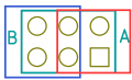
Jumpers Setting


The jumpers have two sides – A and B. You can choose the serial communication object of XBee module by setting the jumpers. When choose A side, you can make the XBee module communicate with Arduino via serial port; when choose B side, you can make the XBee module communicate with PC via serial port, namely, you can use PC to configure XBee module.
Documents
- Arduino motor shield R3 link here
- All demo code please see here https://github.com/Edragon/Arduino/tree/master/arduino-env/Sketchbook/07_Motor
- Read more information about the working principle on the page Motor
This category currently contains no pages or media.